100 Watt Power Amplifier Circuit Diagram Using Mosfet
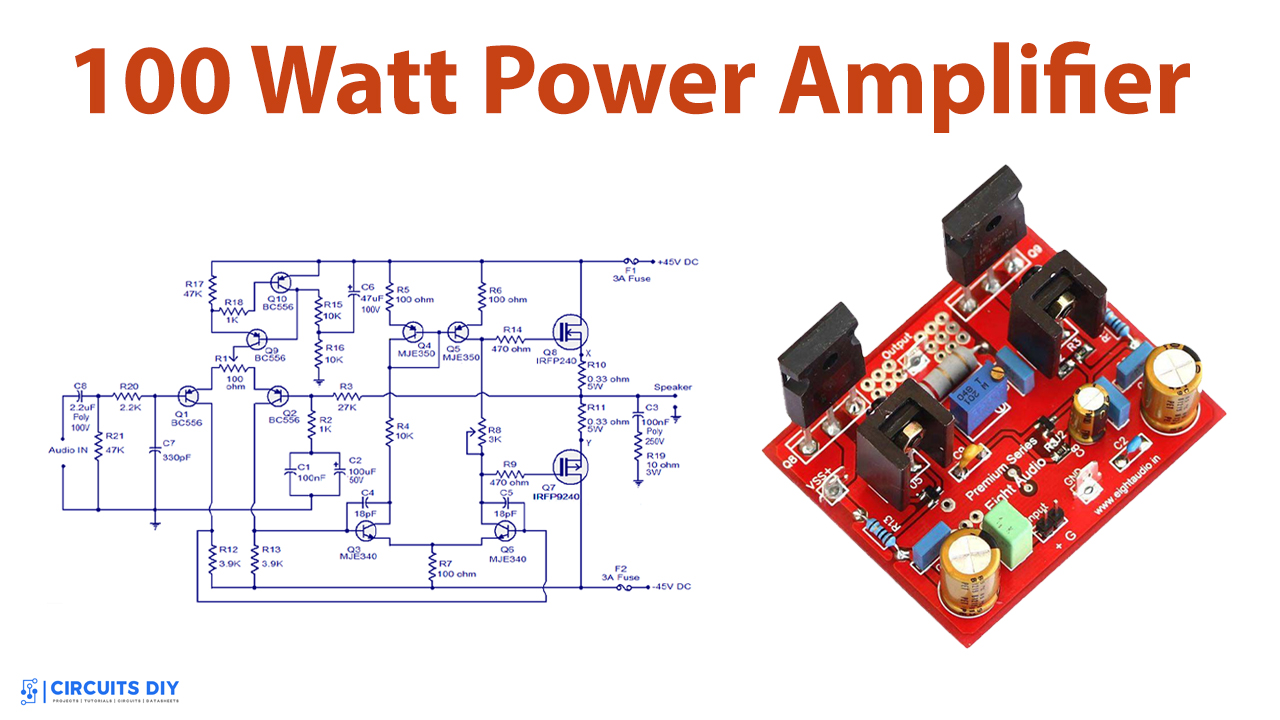
Diy 100 Watt Mosfet Amplifier Circuit With Pcb Homemade Circuit 100 watt power amplifier circuit using mosfet. power amplifier is the part of audio electronics. it is designed to maximize the magnitude of the power f given input signal. in sound electronics, the operational amplifier increases the voltage of the signal, but unable to provide the current, which is required to drive a load. A 100w mosfet power amplifier circuit based on irfp240 and irfp9240 mosfets is shown here. the amplifier operates from a 45 45 v dc dual supply and can deliver 100 watt rms into an 8 ohm speaker and 160 watt rms into a 4 ohm speaker. this hi fi amplifier circuit is suitable for a lot applications like general purpose amplifier, guitar.
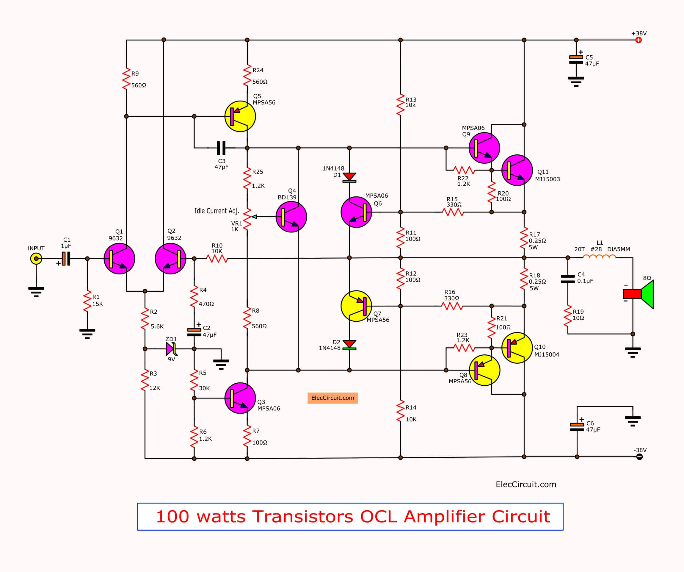
100w Audio Power Amplifier Circuit Diagram 100w mosfet power amplifier circuit. Diy 100 watt mosfet amplifier circuit with pcb. Working explanation. in the mosfet power amplifier circuit, capacitor c8 is the input decoupling capacitor. r20 is used to restrict the input current for transistor q1. resistor r3 and r2 are used to set the gain. while r1 is used to adjust the output voltage. q7 and q8 transistors make the power amplifier of class ab. The 100w power amplifier circuit diagram discussed in this article showcases the usage of mosfet irfp244 and irfp9240, along with mje340, mje350, and mpsa43 transistors in various sections. this circuit design allows for the amplification of weak audio signals to drive speakers effectively. the specifications of each transistor ensure the.
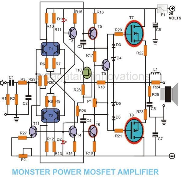
How To Build A 100 Watt Mosfet Amplifier Circuit Simple Design Explore Working explanation. in the mosfet power amplifier circuit, capacitor c8 is the input decoupling capacitor. r20 is used to restrict the input current for transistor q1. resistor r3 and r2 are used to set the gain. while r1 is used to adjust the output voltage. q7 and q8 transistors make the power amplifier of class ab. The 100w power amplifier circuit diagram discussed in this article showcases the usage of mosfet irfp244 and irfp9240, along with mje340, mje350, and mpsa43 transistors in various sections. this circuit design allows for the amplification of weak audio signals to drive speakers effectively. the specifications of each transistor ensure the. This design delivers exceptional harmonic distortion levels of 0.075% at 100 hz and 0.135% at 10 khz when the output power is at least 20 w into 8 ohm. conclusion. the mosfet power amplifier circuit is a simple yet effective design that delivers powerful and high quality audio output. How to design mosfet power amplifier circuits.
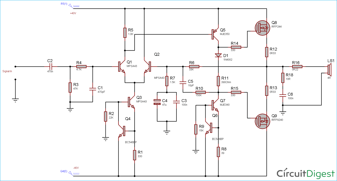
100 Watt Power Amplifier Circuit Diagram Using Mosfet This design delivers exceptional harmonic distortion levels of 0.075% at 100 hz and 0.135% at 10 khz when the output power is at least 20 w into 8 ohm. conclusion. the mosfet power amplifier circuit is a simple yet effective design that delivers powerful and high quality audio output. How to design mosfet power amplifier circuits.
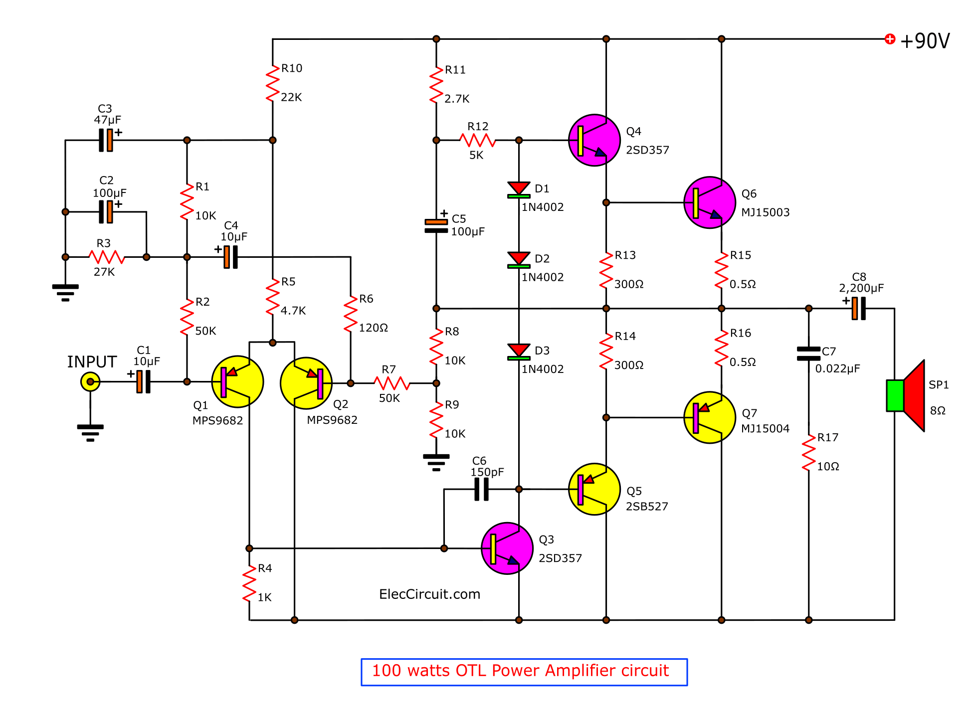
100 W Amplifier Circuit Diagram

Comments are closed.