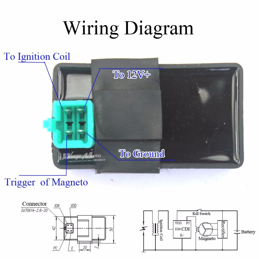
110cc 5 Wire Cdi Wiring Diagram Wiring Digital And Schematic
110cc 5 Pin Cdi Wiring Diagram On a 5 pin cdi system, you will find 5 different colored wires coming out of the cdi unit: green – connects to pickup coil signal input. white – connects to ac input from stator. red – main power source ( 12v from battery) black – main ground ( connection to battery) blue – output to ignition coil. Everrich quad wire harness complete wiring electrics stator coil cdi solenoid relay spark plug for 4 stroke atv 50cc 70cc 90cc 110cc 125cc pit. high power racing performance ac 5 pin cdi box for 90cc 110cc 125cc 140cc pit quad atv. lifan 110 motor wiring diagram honda 70 talk dumont dune riders. need wiring help with 110cc super pocket bike.

Diagram Five Wire Cdi Diagram Mydiagram Online The 110cc 5 pin cdi wiring diagram is an essential tool for any electrical project. by breaking the diagram down into its component parts and understanding the power source, cabling, and connectors and plugs, you can better comprehend exactly what the diagram does and know how to use it for future projects. ignition coil 5 pin cdi box for 50cc. Wiring a cdi involves connecting various wires and components, such as the stator, pickup coil, and ignition coil, in the correct sequence and configuration. this diagram shows you exactly how to wire a 5 pin cdi. each wire is labeled and color coded, making it easy to identify and connect the correct wires. The 5 pin cdi box. the 5 pin cdi comes in the form of a black box, fitted with a male connector at the top. inside of this male connector, there are five different pins that connect to the various parts of the ignition system to provide power to the machine. these five pins connect the timing trigger pulse generator, ignition coil, ignition. Overall, identifying the wires in a 5 wire cdi is an essential step in the installation process. taking the time to understand the functions and colors of each wire will help you connect everything correctly and ensure the proper functioning of your cdi unit. the black wire. the black wire is a vital component in the 5 wire cdi wiring diagram.

Understanding The 110cc 5 Wire Cdi Wiring Diagram A Comprehensiv The 5 pin cdi box. the 5 pin cdi comes in the form of a black box, fitted with a male connector at the top. inside of this male connector, there are five different pins that connect to the various parts of the ignition system to provide power to the machine. these five pins connect the timing trigger pulse generator, ignition coil, ignition. Overall, identifying the wires in a 5 wire cdi is an essential step in the installation process. taking the time to understand the functions and colors of each wire will help you connect everything correctly and ensure the proper functioning of your cdi unit. the black wire. the black wire is a vital component in the 5 wire cdi wiring diagram. The 5 pins on the cdi connector supply power, ground, and signals to control this process. here is a quick overview of each pin’s function: pin 1 – ground. pin 2 – 12vdc from battery via ignition switch and fuses. pin 3 – trigger signal from ac generator stator. pin 4 – switched 12vdc to ignition coil. Step 1: unplug the stator connectors. step 2: remove the left engine cover step 3: disconnect the stator wires from the harness step 4: set multimeter to ohms mode. step 5: test resistance across each stator lead. readings vary widely by specific model and spec, but 1 ohm or less generally indicates a healthy stator.

110cc 5 Pin Cdi Wiring Diagram The 5 pins on the cdi connector supply power, ground, and signals to control this process. here is a quick overview of each pin’s function: pin 1 – ground. pin 2 – 12vdc from battery via ignition switch and fuses. pin 3 – trigger signal from ac generator stator. pin 4 – switched 12vdc to ignition coil. Step 1: unplug the stator connectors. step 2: remove the left engine cover step 3: disconnect the stator wires from the harness step 4: set multimeter to ohms mode. step 5: test resistance across each stator lead. readings vary widely by specific model and spec, but 1 ohm or less generally indicates a healthy stator.

Comments are closed.