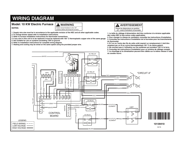
120v Furnace Motor Wiring Diagram

120v Furnace Motor Wiring Diagram Follow the wires from those splices, back to the control board, or check the schematic. that will tell you how to wire everything. according to the new motor white = l1 (neutral), black = high speed, blue = medium speed, red = low speed. check the diagram on the old motor, to figure out which wires are which. Learn how to wire a furnace or ac blower motor with this easy to follow video guide. you will need some basic tools and safety precautions.

120v Furnace Motor Wiring Diagram The furnace blower motor wire diagram typically includes information on the various colors of wires used, as well as their functions. for example, the red wire may be for the power supply, while the black wire could be for grounding. understanding the purpose of each wire is crucial for proper installation and maintenance of the motor. Squirrel cage blowers make great fans. black is ground, white negative and red positive. looks like blue, white and red coming from the motor. read the info on the motor, it should have split capacitor in it, may have to change the wiring from 220 to 110. looks like a 1 4 1 5 horse. ask a local hvac guy, feed his ego and be rewarded. This is about 120 volt blower motor speeds and wire colors! we will go over which speed each wire color is and show you how you can tell the speed by using a. In order to do so, remove the panel holding the circuit board for the system. with the 2 screws removed, gently slide the circuit board out of the system. leave the wires attached for now. we will disconnect the old blower motor in a subsequent step. next, remove the hoses attached to the drain trap, both top and bottom.

120v Furnace Motor Wiring Diagram This is about 120 volt blower motor speeds and wire colors! we will go over which speed each wire color is and show you how you can tell the speed by using a. In order to do so, remove the panel holding the circuit board for the system. with the 2 screws removed, gently slide the circuit board out of the system. leave the wires attached for now. we will disconnect the old blower motor in a subsequent step. next, remove the hoses attached to the drain trap, both top and bottom. In this episode we talk about how to wire your new blower motor. if you would like to find out how to install a blower motor, check out our other video: http. Low voltage wire: low voltage wiring is used for various components in the furnace system, such as control boards, sensors, thermostats, heating, heat pumps, and compressors. the wiring diagram for the heat pump compressor systems typically operates at a lower voltage level, around 24 volts, ensuring safety for these sensitive components.

120v Furnace Motor Wiring Diagram In this episode we talk about how to wire your new blower motor. if you would like to find out how to install a blower motor, check out our other video: http. Low voltage wire: low voltage wiring is used for various components in the furnace system, such as control boards, sensors, thermostats, heating, heat pumps, and compressors. the wiring diagram for the heat pump compressor systems typically operates at a lower voltage level, around 24 volts, ensuring safety for these sensitive components.

Comments are closed.