12vdc 24vdc Battery Charger Center Tapped Transformer Wiring Diagram

12vdc 24vdc Battery Charger Center Tapped Transformer Wiring Diagram A simple battery charger using center tapped transformer with 2 output voltages, 12vdc 24vdc @ 10 amps rating. can be monitored with a digital volt ammeter d. How to get 24v from a 12 0 12 transformer. for getting 24v output using a 12 0 12 transformer just connect both side terminal wires of the transformer with the diodes and keep the middle terminal of the transformer not connected anywhere. this connection gives us a full wave 24v output using a 12 0 12 transformer. no current will be reduced.

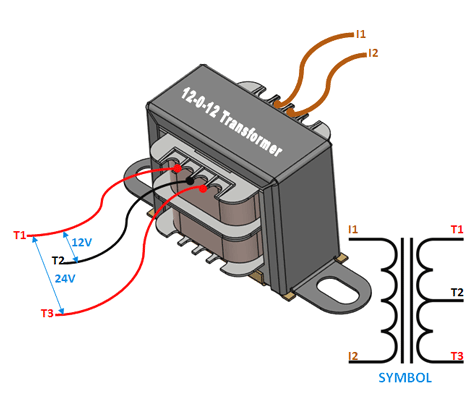
12 0 12 Centre Tapped Transformer Wiring Specifications How To Use It You can use a 15 0 15 secondary like this: it works slightly better than a non centre tapped 15v secondary at producing the correct voltage. a single 15 volt secondary will produce 21.21 volts minus two forward diode drops = ~19.8 volts whereas the split secondary will produce 21.21 volts minus one diode drop = ~20.5 volts. A 12v 24v battery charger circuit diagram is mainly composed of a transformer, rectifier, filter capacitor, and charging relays. the transformer is designed to step up the voltage of a power supply to a higher voltage for efficient charging. a rectifier is then used to convert the ac output from the transformer to dc voltage output. These are the input wires for the transformer, it is connected to the phase and neutral of ac mains. 2. t1 and t3. there are the output terminals of the transformer, the voltage across it will be 24v ac. 3. t2. this is the centre tapped wire of the transformer; this wire can be combined with either t1 or t3 to get 12v ac across it. A good battery charger tapers off when the battery voltage is above about 14v. for this to function, d6 is a 5.1v shunt zener regulator that puts out 5.1v relative to the positive rail. it is biased via r8. ramp generator c1 and r4 form a ramp generator that generates a negative going sawtooth voltage (relative to the positive rail).

12 Volt Transformer Wiring Diagram These are the input wires for the transformer, it is connected to the phase and neutral of ac mains. 2. t1 and t3. there are the output terminals of the transformer, the voltage across it will be 24v ac. 3. t2. this is the centre tapped wire of the transformer; this wire can be combined with either t1 or t3 to get 12v ac across it. A good battery charger tapers off when the battery voltage is above about 14v. for this to function, d6 is a 5.1v shunt zener regulator that puts out 5.1v relative to the positive rail. it is biased via r8. ramp generator c1 and r4 form a ramp generator that generates a negative going sawtooth voltage (relative to the positive rail). Any ac powered battery charger will need rectifiers somewhere to convert to dc. if you look at this transformer the low voltage output will have one of two setups: 1. there will be three wires coming out of the transformer secondary with two of the wires connected to their own individual diodes and two legs of the diodes will be connected to. Share. more. this is an extension of the earlier 12v scr battery charger. it is surprisingly easy to increase the output voltage to 24v, but there are both obvious and subtle differences to consider. the most obvious difference is the transition from full wave center tapped to a full wave bridge configuration. in this case, the full wave bridge.

Comments are closed.