16 Pin All Car Obd Connector Wiring Digram

J1939 Data Link Connector Wiring Diagram Obd ii is a set of specifications for monitoring and reporting on engine performance in modern automobiles. diesel (compression ignition) vehicles were not required to support obd until 2004. some pre 2001 petrol vehicles and pre 2004 diesel vehicles have a 16 pin connectors but they may not be obd ii or eobd compliant. There are two main types of obd2 connectors: type a connectors: found in small vehicles like cars. they have a 12v output voltage and a baud rate of approximately 500,000 bauds. type b connectors: found in medium sized and heavy vehicles. they have a 24v output voltage and a maximum baud rate of 250,000 bauds.

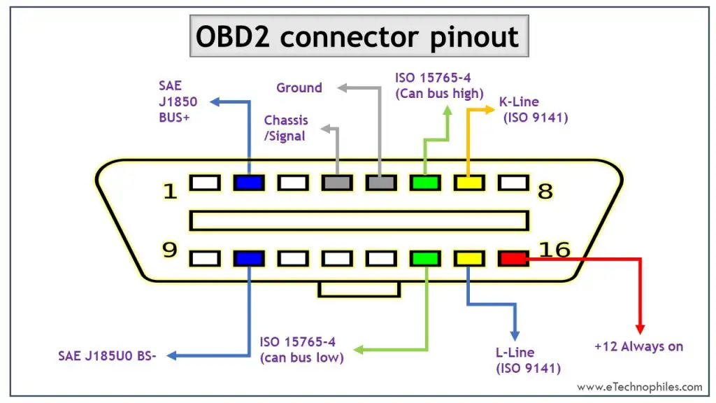
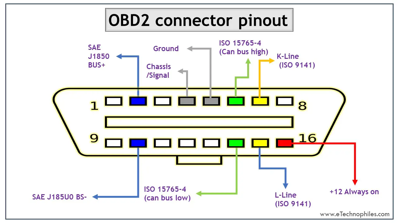
16 Pin Obd2 Connector Color Wire Diagram The obd 16 pin connector is a standardized connector used in vehicles for communicating with the vehicle’s onboard diagnostics system. it is also known as the obd ii connector. the connector is used by diagnostic tools and scanners to retrieve information from the vehicle’s computer system. the obd 16 pin connector pinout diagram provides a. The on board diagnostics (obd) system in vehicles uses a standardized 16 pin connector for communication between the vehicle’s electronic control unit (ecu) and an external diagnostic tool. the 16 pin connector is typically located under the dashboard on the driver’s side of the vehicle. it provides access to a wide range of diagnostic. Iso15765 (can) obdii connector pinout diagram. iso15765 4 (can bus) is mandatory for all 2008 and later vehicles sold in the us. this protocol uses pins 6 and 14. there are four variants of iso15765 however and they can sometimes be confused as different protocols. 16 pin (obd) connector full information with wiring diagram| diagnostic connector (obd) wiring discus#16pinobdconnector#wiringdiagram#atozcarsystem.

Obd Connector Pinout Types Codes Explained Off The Best Porn Website Iso15765 (can) obdii connector pinout diagram. iso15765 4 (can bus) is mandatory for all 2008 and later vehicles sold in the us. this protocol uses pins 6 and 14. there are four variants of iso15765 however and they can sometimes be confused as different protocols. 16 pin (obd) connector full information with wiring diagram| diagnostic connector (obd) wiring discus#16pinobdconnector#wiringdiagram#atozcarsystem. Understanding the basics of the obd2 port wiring diagram is crucial for diagnosing and troubleshooting any potential issues with your vehicle. the obd2 port wiring diagram typically consists of 16 pins, each serving a specific purpose. these pins are arranged in a specific pattern and have different functions, such as providing power, ground. The obd port can found on the dashboard near the steering wheel of every car. the position of the port varies based on the manufacturer and is normally hidden in a blind spot for aesthetic reasons. once you find the port hook up the connector and connect the other end to stn1110 obd uart board. then the uart board is connected to a computer.

16 Pin Obd Connector Pinout Understanding the basics of the obd2 port wiring diagram is crucial for diagnosing and troubleshooting any potential issues with your vehicle. the obd2 port wiring diagram typically consists of 16 pins, each serving a specific purpose. these pins are arranged in a specific pattern and have different functions, such as providing power, ground. The obd port can found on the dashboard near the steering wheel of every car. the position of the port varies based on the manufacturer and is normally hidden in a blind spot for aesthetic reasons. once you find the port hook up the connector and connect the other end to stn1110 obd uart board. then the uart board is connected to a computer.

Comments are closed.