2 Speed Cooling Fan Wiring Diagram

2 Speed Cooling Fan Wiring Diagram For Your Needs Section 1: understanding the basics of 2 speed fans. in this section, we will cover the fundamental concepts behind 2 speed fans and how they operate. understanding these basics will provide a foundation for successfully wiring a 2 speed fan. definition: a 2 speed fan is a type of fan that can operate at two different speeds – typically a low. Step 4: install the switch. mount the two speed switch in a convenient location. connect the live wire from the power supply to the input side of the switch. connect the output side of the switch to the live wires that are connected to the fan motor. this will allow you to control the speed of the fan using the switch.

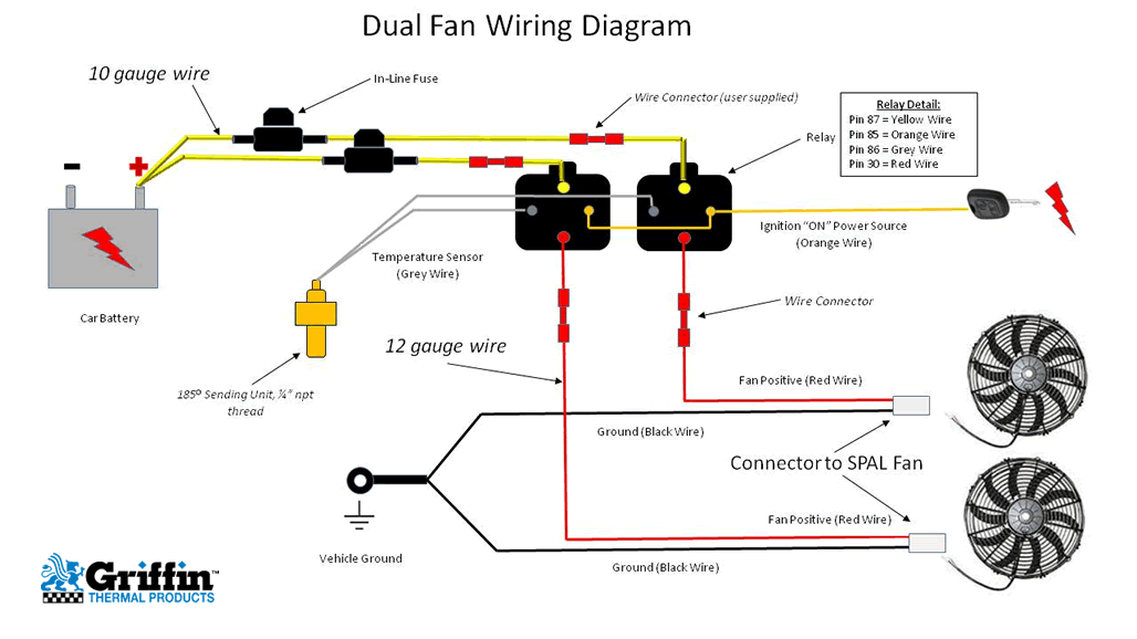
35 New 2 Speed Cooling Fan Wiring Diagram How to wire up a 2 speed ford taurus electric fanthe relays i used is the zettler az979 1a 12de for low speed and az979 1c 12d for hi speed. than use a 30 am. Optionally, a single high current relay could be used to control both fans. the supplied diagram below using dual relays with a single temp sensor is both the most reliable and easiest method we've found for wiring dual fans. it uses our 40 amp electric relay kit and electric fan sensor. the relay isolates the high amp load of the fan circuit. The wiring diagram for a two speed electric fan typically includes a power source, a relay, a temperature switch, and the fan motor. the power source can be connected directly to the battery or through a fuse box, depending on the setup. the relay acts as a switch, controlling the power flow to the fan motor. 2 speed engine cooling fan wiring. i'm looking for some advice on hooking up a 2 speed cooling fan in my hotrod. the fan i have has 3 wires, a ground and 2 positives. low speed is activated by one positive wire and high speed is activated when both positive wires are connected. i will be controlling them with an on off on toggle switch and 2.

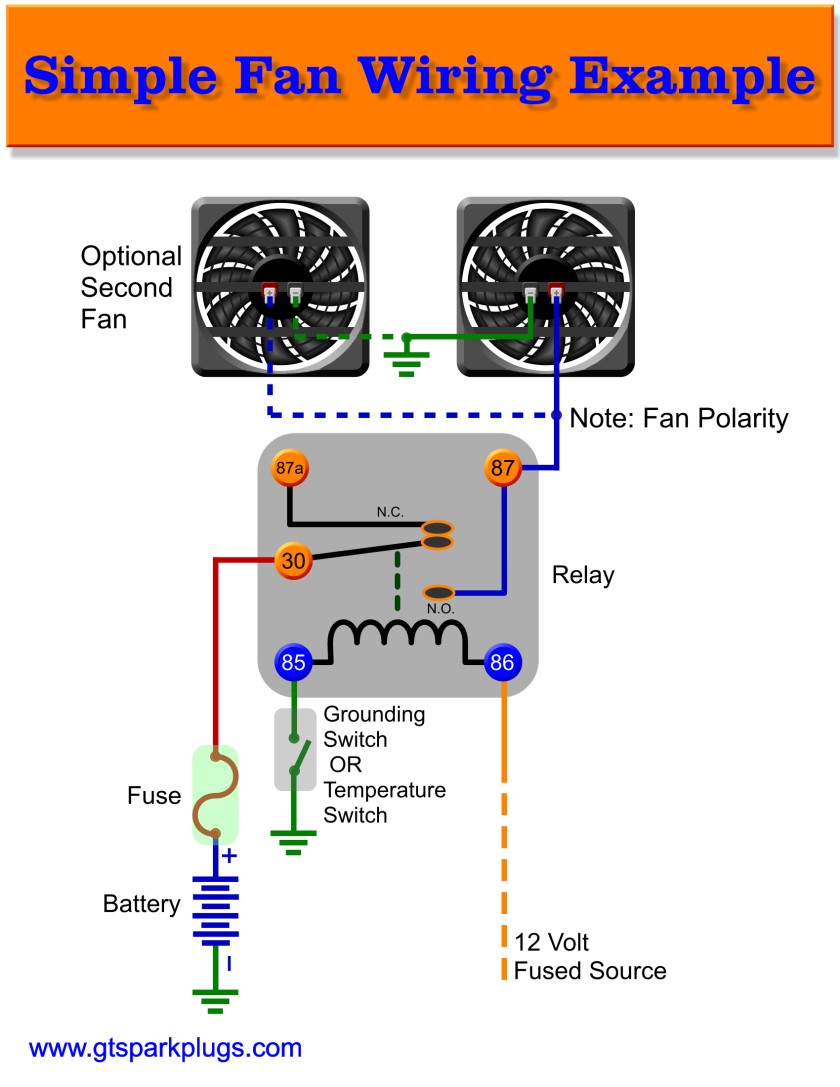
35 New 2 Speed Cooling Fan Wiring Diagram The wiring diagram for a two speed electric fan typically includes a power source, a relay, a temperature switch, and the fan motor. the power source can be connected directly to the battery or through a fuse box, depending on the setup. the relay acts as a switch, controlling the power flow to the fan motor. 2 speed engine cooling fan wiring. i'm looking for some advice on hooking up a 2 speed cooling fan in my hotrod. the fan i have has 3 wires, a ground and 2 positives. low speed is activated by one positive wire and high speed is activated when both positive wires are connected. i will be controlling them with an on off on toggle switch and 2. The first step in wiring a two speed fan is to locate a suitable mounting location for the fan itself. it should be placed in such a way that it provides optimal airflow to the engine. once you have found a suitable location, you can proceed with connecting the necessary wires. start by connecting the positive wire from the fan to the positive. Start your wiring project by taking both of the positive wires from the fans and run them to the yellow wires on each relay (tab 87). then connect switched power (usually from your ignition switch), to the blue wires on both relays (tab 86). next, splice together both black wires from the relays (tab 85) and connect them to the thermostat.

2 Speed Electric Cooling Fan Wiring Diagram Youtube The first step in wiring a two speed fan is to locate a suitable mounting location for the fan itself. it should be placed in such a way that it provides optimal airflow to the engine. once you have found a suitable location, you can proceed with connecting the necessary wires. start by connecting the positive wire from the fan to the positive. Start your wiring project by taking both of the positive wires from the fans and run them to the yellow wires on each relay (tab 87). then connect switched power (usually from your ignition switch), to the blue wires on both relays (tab 86). next, splice together both black wires from the relays (tab 85) and connect them to the thermostat.

Comments are closed.