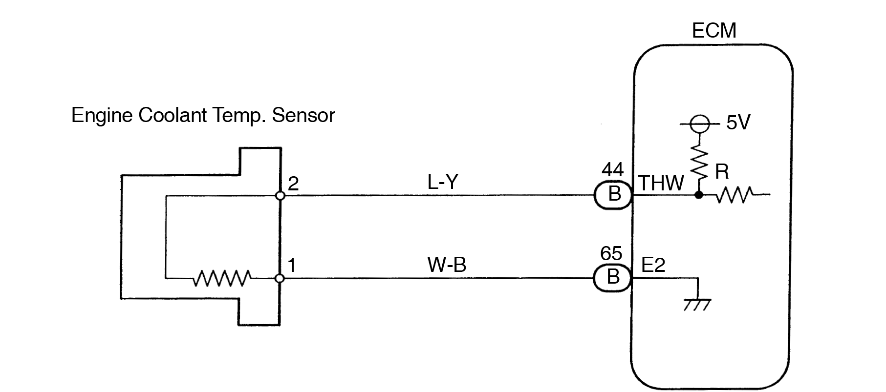
2 Wire Temp Sensor Coolant Temperature Sensor Wiring Diagr

2 Wire Temp Sensor Wiring Diagram 3 wire coolant temperature sensor wiring diagram. the two wires, a “5 volt reference”, and a “ground wire” go to the ecu, and the third wire “earth 1 wire for temp gauge” goes to the cluster mounted temperature gauge by providing an earth link to the temperature gauge. in three wire coolant temp sensors, the ecu does not control the. The coolant temp sensor wiring diagram illustrates the electrical connections for the sensor. it typically includes the wire colors, connector pinouts, and any related components in the circuit. the diagram acts as a guide for mechanics, technicians, and car enthusiasts who need to understand how the sensor is wired to ensure accurate readings.

2 Wire Temp Sensor Coolant Temperature Sensor Wiring Step 3: prepare the wires. now, it’s time to prepare the wires for installation. start by cutting the appropriate length of wire needed to connect the gauge to the temperature sensor. strip the ends of the wire to expose the metal, allowing for proper connection. You're confusing the temperature sender (one wire and a grounded body) and the ect sensor (two wires, not grounded to the block). the sender operates the gauge in the instrument cluster. the sensor sends info to the ecu. he's not having monumental problems here. just needs to replace the pigtail on the wiring harness. The 2 wire temp sensor is designed to be robust and reliable, with a long service life. each 2 wire temp sensor is also equipped with a ground wire, which is used to ensure proper grounding of the device. 2 wire temp sensor coolant temperature sensor wiring diagram. a wiring diagram is essential for correctly connecting a 2 wire temp sensor to. Measure the temperature of the surface of the engine using either a cooking thermometer or an infrared thermometer. note the temperature reading of the surface of the engine. set the digital multimeter to the resistance settings. connect both wires to the connecting terminals of the ect sensor and measure the resistance.

Comments are closed.