2 Wire Temp Sensor Wiring Diagram вђ A Comprehensive Guide Moo Wiri

2 Wire Temp Sensor Wiring Diagram A 2 wire temp sensor wiring diagram is a diagram that shows the connection of two wires used to measure a particular temperature. the two wires are connected to a thermistor, which is a device that measures temperature. the thermistor has a negative and a positive terminal. when current passes through the thermistor, the temperature is measured. A wiring diagram is essential for ensuring that the 2 wire temp sensor is connected correctly and that the power supply is connected to the correct circuit. by following the instructions outlined in the wiring diagram, it is possible to ensure that the 2 wire temp sensor is connected properly and that the engine can be safely operated.

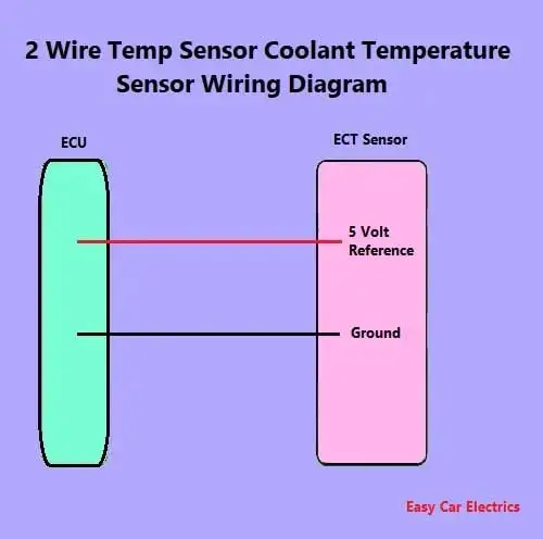
2 Wire Temp Sensor Coolant Temperature Sensor Wiring Diagramо A two wire temperature sensor is a type of sensor that is commonly used to measure temperature in various applications. it works by utilizing two wires that are connected to a temperature sensing element, such as a thermistor or a resistance temperature detector (rtd). these wires are typically made of conductive material, such as copper or. A 2 wire pt100 is a type of temperature sensor that uses a platinum resistance element to measure temperature. it is called a “2 wire” sensor because it only requires two wires for its operation. the pt100 sensor is designed to have a resistance of exactly 100 ohms at 0 degrees celsius. as the temperature changes, the resistance of the. The wiring diagram of a 2 wire sensor typically includes two wires: a power wire and a ground wire. the power wire supplies the necessary voltage to the sensor, while the ground wire provides the return path for the current. in some cases, the power wire may also be used for transmitting the data or signal from the sensor. Step 2: identify the correct wires. locate the wires that need to be connected to the ls 2 wire temp sensor. the sensor will have two wires, typically colored black and yellow. consult the wiring diagram or manual for your specific ls engine to identify the correct wires.

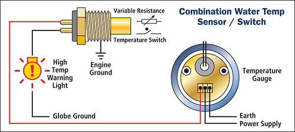
2 Wire Temp Sensor Coolant Temperature Sensor Wiring Diagramо The wiring diagram of a 2 wire sensor typically includes two wires: a power wire and a ground wire. the power wire supplies the necessary voltage to the sensor, while the ground wire provides the return path for the current. in some cases, the power wire may also be used for transmitting the data or signal from the sensor. Step 2: identify the correct wires. locate the wires that need to be connected to the ls 2 wire temp sensor. the sensor will have two wires, typically colored black and yellow. consult the wiring diagram or manual for your specific ls engine to identify the correct wires. 3 wire coolant temperature sensor wiring diagram. the two wires, a “5 volt reference”, and a “ground wire” go to the ecu, and the third wire “earth 1 wire for temp gauge” goes to the cluster mounted temperature gauge by providing an earth link to the temperature gauge. in three wire coolant temp sensors, the ecu does not control the. The tolerance of a temperature sensor wire’s resistance value is a measure of the maximum allowable deviation from the nominal resistance value. a tighter tolerance indicates a higher degree of accuracy and consistency in the temperature measurement. for platinum rtds, a typical tolerance is ±0.1%, meaning that the actual resistance value.

Coolant Temp Sensor Wiring 3 wire coolant temperature sensor wiring diagram. the two wires, a “5 volt reference”, and a “ground wire” go to the ecu, and the third wire “earth 1 wire for temp gauge” goes to the cluster mounted temperature gauge by providing an earth link to the temperature gauge. in three wire coolant temp sensors, the ecu does not control the. The tolerance of a temperature sensor wire’s resistance value is a measure of the maximum allowable deviation from the nominal resistance value. a tighter tolerance indicates a higher degree of accuracy and consistency in the temperature measurement. for platinum rtds, a typical tolerance is ±0.1%, meaning that the actual resistance value.

Comments are closed.