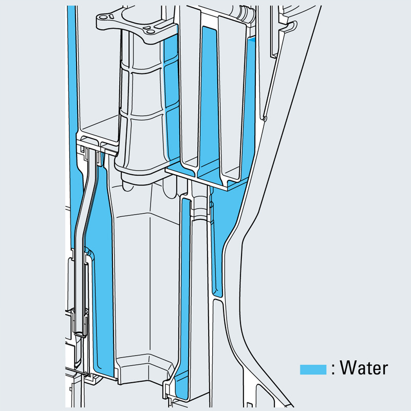
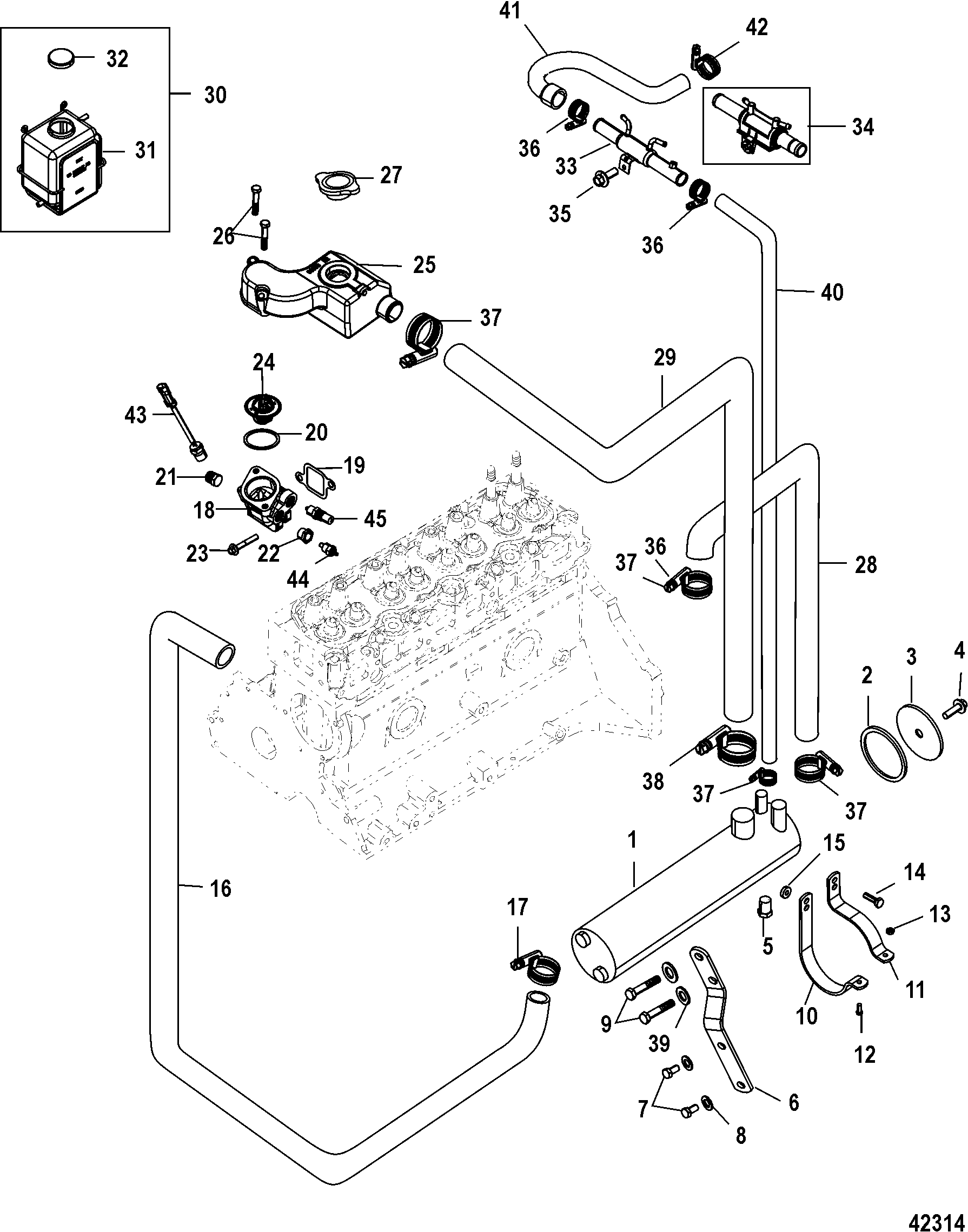
2004 60hp Mercury Outboard Cooling System Diagrame

Mercury 60hp 2 Stroke Wiring Diagram The cooling system in a mercury outboard motor is a critical component that plays a vital role in maintaining the engine’s optimal operating temperature. it is essential for the proper functioning and longevity of the motor. without a properly functioning cooling system, the engine can overheat, leading to severe damage and potential breakdowns. Service manual 40 90 hp cooling system [hose routing and water flow diagrams] johnson evinrude, omc. factory service manual. 5008328. added september 4, 2020 at 9:21 pm updated december 8, 2020 at 7:27 pm.

Diagram Honda Outboard Cooling Diagram Mydiagram Online Call us at (405) 533 3812 or send us an email at sales@perfprotech for more details, there is no better deal available on mercury outboard parts, guaranteed! shop online to buy parts for mercury outboard motors. lookup mercury outboard parts catalogs by year, serial or model number. ppt is an a bbb rated authorized mercury marine parts. The cooling system on an outboard is a very simple and compact application. water is inducted through the lower unit by a water pump impeller, and then forced upward to circulate throughout the powerhead, and eventually exits through the exhaust system. there are a couple of things pertaining to the outboard cooling system that need regular. Page 60: flushing the cooling system flush the internal water passages of the outboard with fresh water after each use in salt, polluted, or muddy water. this will help prevent a buildup of deposits from clogging the internal water passages. use a mercury precision or quicksilver accessory (or equivalent) flushing attachment. 5. check for a steady stream of water flowing out of the water pump indicator hole. continue flushing the outboard for 3 to 5 minutes, carefully monitoring water supply at all times. 6. stop the engine, turn off the water, and remove the flushing attachment. reinstall the propeller.

Johnson Outboard Cooling System Diagram Shamleeaeden Page 60: flushing the cooling system flush the internal water passages of the outboard with fresh water after each use in salt, polluted, or muddy water. this will help prevent a buildup of deposits from clogging the internal water passages. use a mercury precision or quicksilver accessory (or equivalent) flushing attachment. 5. check for a steady stream of water flowing out of the water pump indicator hole. continue flushing the outboard for 3 to 5 minutes, carefully monitoring water supply at all times. 6. stop the engine, turn off the water, and remove the flushing attachment. reinstall the propeller. 75 115 125 90. view and download mercury 60 manual online. 60 outboard motor pdf manual download. also for: 75, 115, 125, 90. The document outlines sections in a service manual for outboard motors. section 1 provides important specifications and information. sections 2 4 cover electrical systems, fuel injection, and the powerhead. sections 5 7 address the mid section, lower unit, and attachments linkages. section 8 includes color diagrams. each section contains subsections on specific components and systems.

Closed юааcoolingюаб юааsystemюаб юааmercuryюаб юааoutboardюаб Motor Parts Vanтащs Sport Center 75 115 125 90. view and download mercury 60 manual online. 60 outboard motor pdf manual download. also for: 75, 115, 125, 90. The document outlines sections in a service manual for outboard motors. section 1 provides important specifications and information. sections 2 4 cover electrical systems, fuel injection, and the powerhead. sections 5 7 address the mid section, lower unit, and attachments linkages. section 8 includes color diagrams. each section contains subsections on specific components and systems.
Marine 2 Stroke Engine Diagram The Two Stroke Diesel Cycle

Comments are closed.