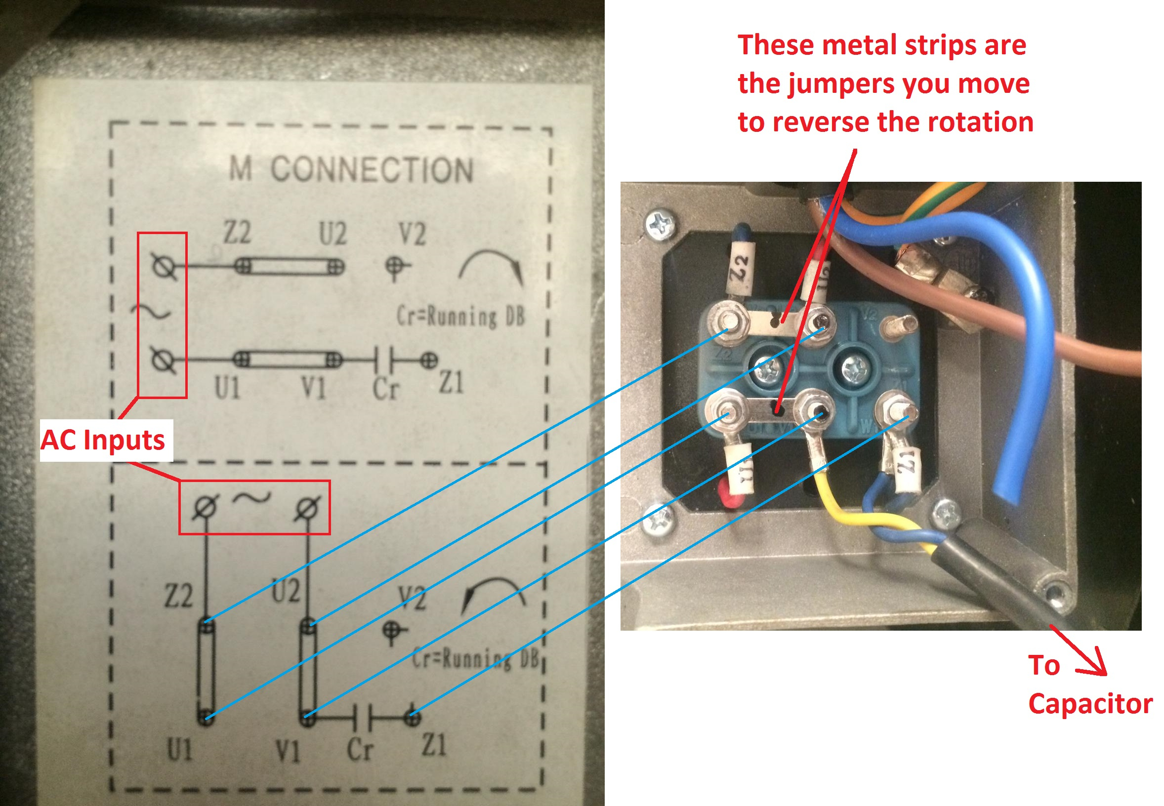
220 Volt Single Phase Motor Wiring

220v Single Phase Wiring Diagram Greenist Step 3. wiring 220 volt boxes and motors is serious business. connect the two top terminals on the switch to the l1 and l2 connections in the motor's electrical enclosure. each of the two top terminals represents one of the opposite poles of the 220 volt power circuit, as do the two bottom terminals. when the switch is turned on, one phase on. Permanent split phase capacitor motor wiring diagram. just as its name implies, this single phase motor diagram will work with a split phase generated by a capacitor. the capacitance from the capacitor and the reactance from the winding will shift the phase to some extent. below is the permanent capacitor single phase motor wiring diagram.

Wire A 220 Volt Single Phase Motor In this video, jamie shows you how to read a wiring diagram and the basics of hooking up an electric air compressor motor. these tips can be used on most ele. In order to properly wire a single phase motor, it is important to understand the wiring diagram and the connections required. the wiring diagram will provide the necessary information about the motor’s terminals, the starting and running capacitors (if applicable), and the direction of rotation. it is crucial to follow the wiring diagram and. The motor wiring diagram provides a visual representation of the electrical connections for a single phase motor. it illustrates how the different components, such as the power supply, start capacitor, run capacitor, centrifugal switch, and winding connections, are connected to each other. typically, single phase motors have two types of. How to wire single phase motor with capacitor. you will find out how to identify to main and auxilliary winding and change motor rotation.start capacitor, ru.

Single Phase Motor Schematic Diagram The motor wiring diagram provides a visual representation of the electrical connections for a single phase motor. it illustrates how the different components, such as the power supply, start capacitor, run capacitor, centrifugal switch, and winding connections, are connected to each other. typically, single phase motors have two types of. How to wire single phase motor with capacitor. you will find out how to identify to main and auxilliary winding and change motor rotation.start capacitor, ru. A typical 220 volt motor wiring diagram will include the following: power supply: the power supply for a 220 volt motor is typically provided by two separate 110 volt lines, which are commonly referred to as l1 and l2. these lines are connected to the motor through a main power disconnect switch and a circuit breaker. The basic components of a 220 motor wiring diagram include the power supply, the motor, and a control box or switch. the power supply will consist of three wires: a hot wire, a neutral wire, and a ground wire. these wires will connect to the corresponding terminals on the motor and control box, ensuring proper electrical connection.

Comments are closed.