230 Volt 3 Phase Motor Wiring Diagram Wiring Diagram

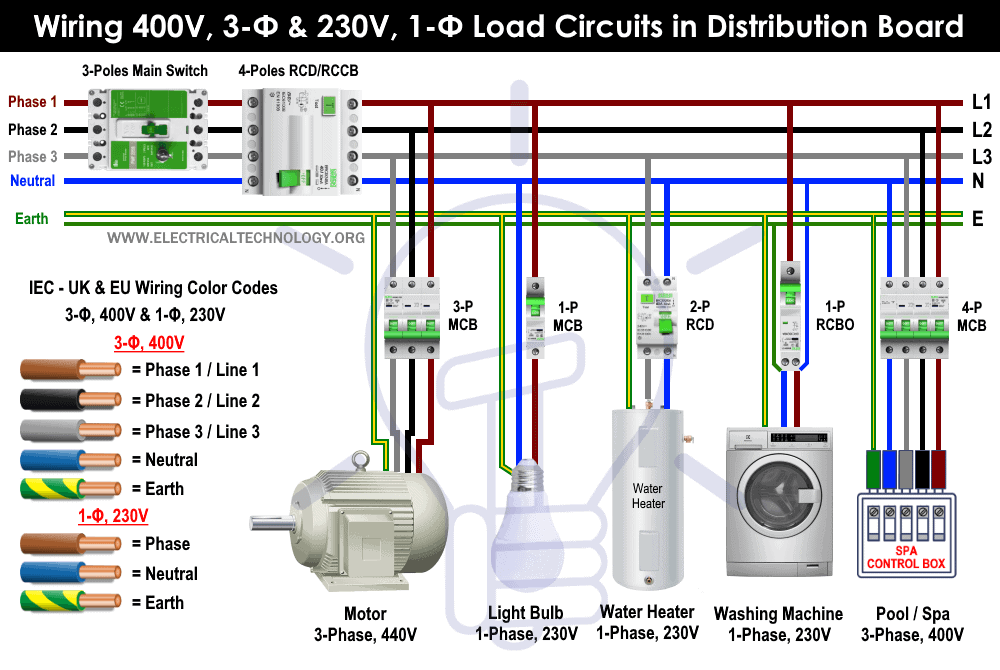
230 Volt 3 Phase Wiring Diagram Step 3: connect the three phases. start by connecting the three phases (l1, l2, l3) to their respective terminals on the motor. use wire nuts to secure the connections and make sure the wires are stripped to the appropriate length for a solid connection. The wiring diagram of a 230 volt motor shows the connections and components required for its proper operation. it typically includes labels for the various terminals, such as the power supply terminals, starting and running capacitor connections, and the motor windings. this diagram serves as a guide for electricians and technicians when.

3 Phase Motor Wiring Diagrams A 230 volt 3 phase motor wiring diagram is simply a schematic showing the connections between different components. this type of wiring diagram includes alternating current (ac) motors and is used in installation, diagnostics, and troubleshooting for the specific motor configuration. detailed components identification. below is a table. The three main components of a 3 phase wiring diagram for motors are: power supply: the diagram shows the three phase power supply, typically labeled as l1, l2, and l3. these represent the three separate phases of the power source. motor: the diagram illustrates the motor as a single unit with labeled terminals. Step 3: turn off the power: ensure that the power to the circuit is turned off before starting the wiring process. this will help prevent any accidents or electrical shocks. step 4: connect the ground wire: start by connecting the ground wire from the motor to the grounding terminal or screw on the motor housing. The 230v 3 phase motor wiring diagram is a comprehensive guide that helps technicians and engineers understand how to properly connect, install, and maintain 230v 3 phase motors. the diagram accurately illustrates how to connect the three phase motors in the most efficient way possible. it also shows which cable is the live, neutral, and ground.

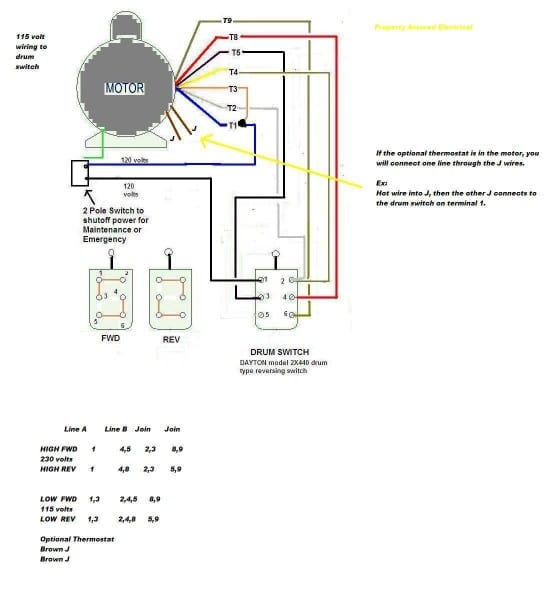
3 Phase Motor Wiring Diagrams 230v Step 3: turn off the power: ensure that the power to the circuit is turned off before starting the wiring process. this will help prevent any accidents or electrical shocks. step 4: connect the ground wire: start by connecting the ground wire from the motor to the grounding terminal or screw on the motor housing. The 230v 3 phase motor wiring diagram is a comprehensive guide that helps technicians and engineers understand how to properly connect, install, and maintain 230v 3 phase motors. the diagram accurately illustrates how to connect the three phase motors in the most efficient way possible. it also shows which cable is the live, neutral, and ground. W2 cj2 ui vi wi w2 cj2 ui vi wi a cow voltage y high voltage z t4 til t12 10 til t4 t5 ali l2 t12 ti blu t2 wht t3.org t4 yel t5 blk t6 gry t7 pnk. In a three phase motor, the star connection is one of the common ways to wire the motor. in this connection, the three ends of the motor windings are connected together to form a star shape. the three other ends, also known as the line terminals, are connected to the three phase power supply. when the motor is running in star connection, the.

230 Volt Electric Motor Wiring Diagram W2 cj2 ui vi wi w2 cj2 ui vi wi a cow voltage y high voltage z t4 til t12 10 til t4 t5 ali l2 t12 ti blu t2 wht t3.org t4 yel t5 blk t6 gry t7 pnk. In a three phase motor, the star connection is one of the common ways to wire the motor. in this connection, the three ends of the motor windings are connected together to form a star shape. the three other ends, also known as the line terminals, are connected to the three phase power supply. when the motor is running in star connection, the.

Comments are closed.