240v Circuit Leg Diagram

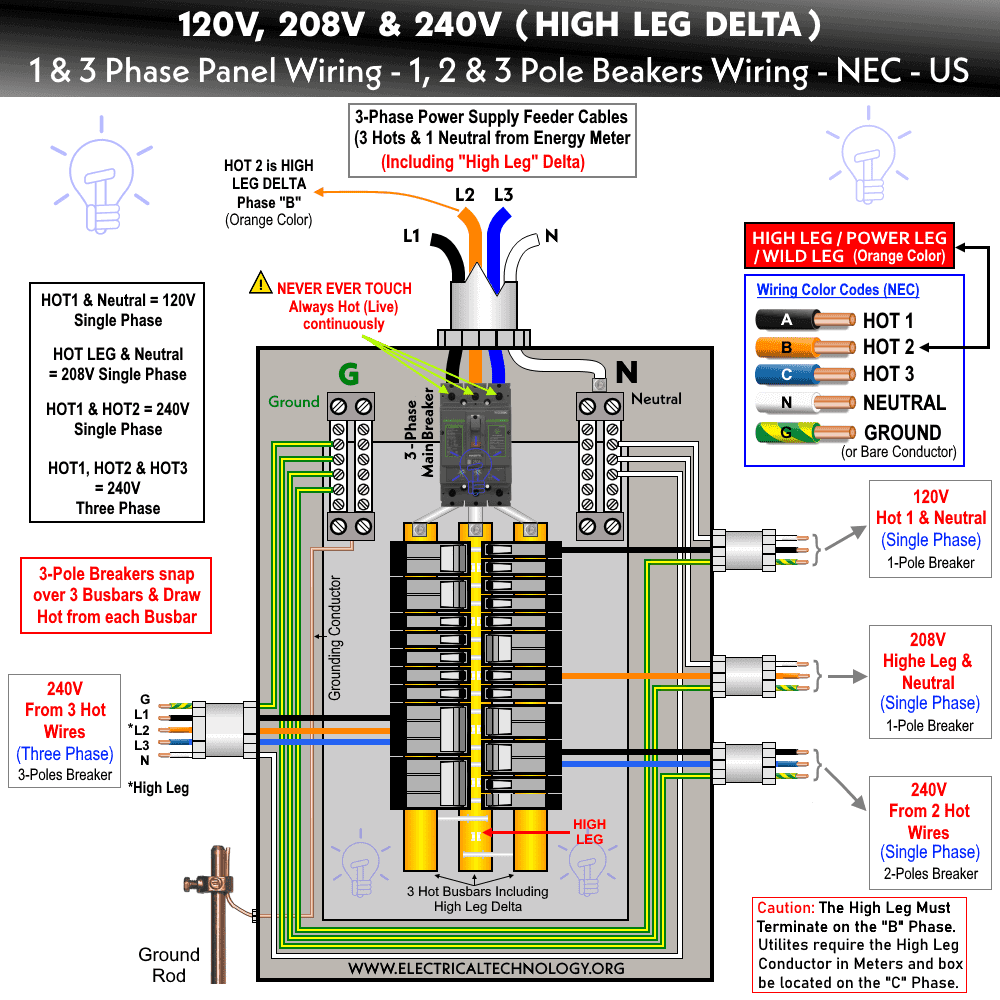
240v Circuit Leg Diagram Voltage between high leg and neutral = 1 2 x 220v x √3 = 208v (1 Φ). voltage between two hot phases = 120v x 2 = 240v (1 Φ). voltage between three phases = 240v (3 Φ). these are the general setup and may vary and depend on the installation e.g. neutral wire may be needed for three phase 240v outlets etc. Short answer: it's because the two, 180 degrees out of phase, feed wires essentially take turns being the return wire every time the phase switches. 240v is the difference between them, and so when leg 1 is at 120v the other leg is at 120v and power is flowing from leg 1 to leg 2, but half a cycle later they are swapped and the power is flowing in the opposite direction, with leg1 acting as.

3 Phase 240v Wiring Diagram We can get two 120v supplies, three 240v supplies, and a 208v supply by employing a high leg delta connection. high leg or orange leg refers to the phase having a 208v supply to the ground. wherever a connection is made, this conductor must be permanently marked with an orange exterior finish. Phasor diagram showing 240 v delta and center tapped phase (a–c) creating two 120 v pairs. consider the low voltage side of a 120 240 v high leg delta connected transformer, where the b phase is the high leg. the line to line voltage magnitudes are all the same: = = =. The following figure shows a typical breaker box panel for 120v and 240v circuits. there are three wires entering the main panel from the energy meter viz: hot 1 or line 1 = black color. hot 2 or line 2 = red color (for illustration purpose only) neutral = white color. click image to enlarge. The 240 volt components use both hot legs. again, let’s think back to what a meter is actually reading. if you check each leg of a 240 volt residential circuit to ground, you will read 120 volts. it is the differential between 120 and 120 that gives you 240 volts when you check leg to leg on a contactor at a condenser… except when you don.

240v Circuit Leg Diagram The following figure shows a typical breaker box panel for 120v and 240v circuits. there are three wires entering the main panel from the energy meter viz: hot 1 or line 1 = black color. hot 2 or line 2 = red color (for illustration purpose only) neutral = white color. click image to enlarge. The 240 volt components use both hot legs. again, let’s think back to what a meter is actually reading. if you check each leg of a 240 volt residential circuit to ground, you will read 120 volts. it is the differential between 120 and 120 that gives you 240 volts when you check leg to leg on a contactor at a condenser… except when you don. As the power coming into most panels in the united states has two 120v lines that are 180 degrees out of phase (sometimes referred to as split phase). by tapping into both of those hot wires, you get a 240v differential between the two lines at their peaks. once you have the breaker that is connected to both hot lines, you will need either two. Connect the hot wires. connect each hot circuit wire to one of the terminals on the new 240 volt circuit breaker. depending on how the circuit has been installed, these might be two black wires, a black and a red wire, or a black wire plus a white wire marked with black tape to identify it as a hot wire. make sure to insert the wires fully into.

240v Circuit Leg Diagram Vrogue Co As the power coming into most panels in the united states has two 120v lines that are 180 degrees out of phase (sometimes referred to as split phase). by tapping into both of those hot wires, you get a 240v differential between the two lines at their peaks. once you have the breaker that is connected to both hot lines, you will need either two. Connect the hot wires. connect each hot circuit wire to one of the terminals on the new 240 volt circuit breaker. depending on how the circuit has been installed, these might be two black wires, a black and a red wire, or a black wire plus a white wire marked with black tape to identify it as a hot wire. make sure to insert the wires fully into.

Comments are closed.