240v Wiring Schematic

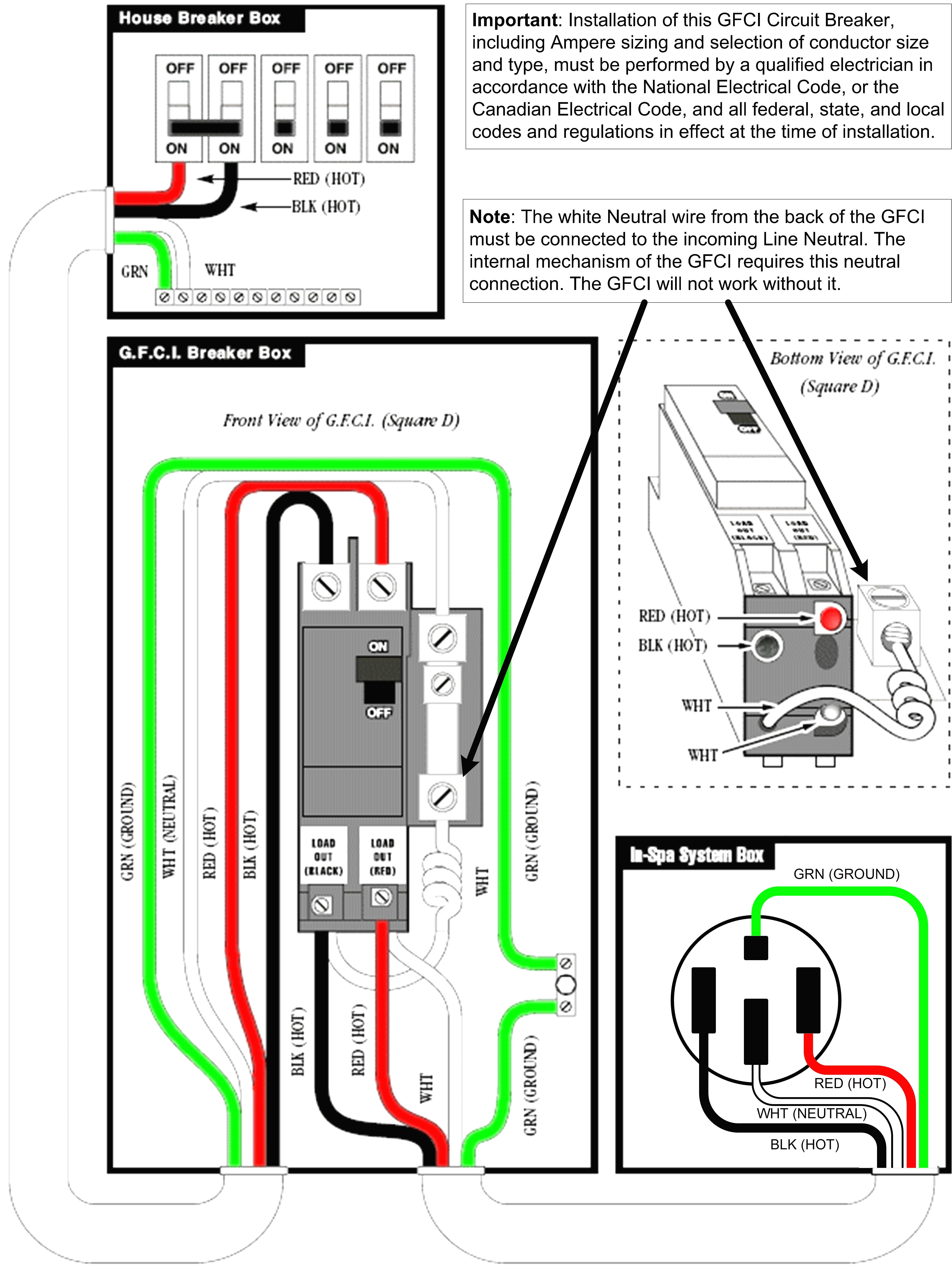
How To Install 240v Wiring Connect the hot wires. connect each hot circuit wire to one of the terminals on the new 240 volt circuit breaker. depending on how the circuit has been installed, these might be two black wires, a black and a red wire, or a black wire plus a white wire marked with black tape to identify it as a hot wire. make sure to insert the wires fully into. As the power coming into most panels in the united states has two 120v lines that are 180 degrees out of phase (sometimes referred to as split phase). by tapping into both of those hot wires, you get a 240v differential between the two lines at their peaks. once you have the breaker that is connected to both hot lines, you will need either two.

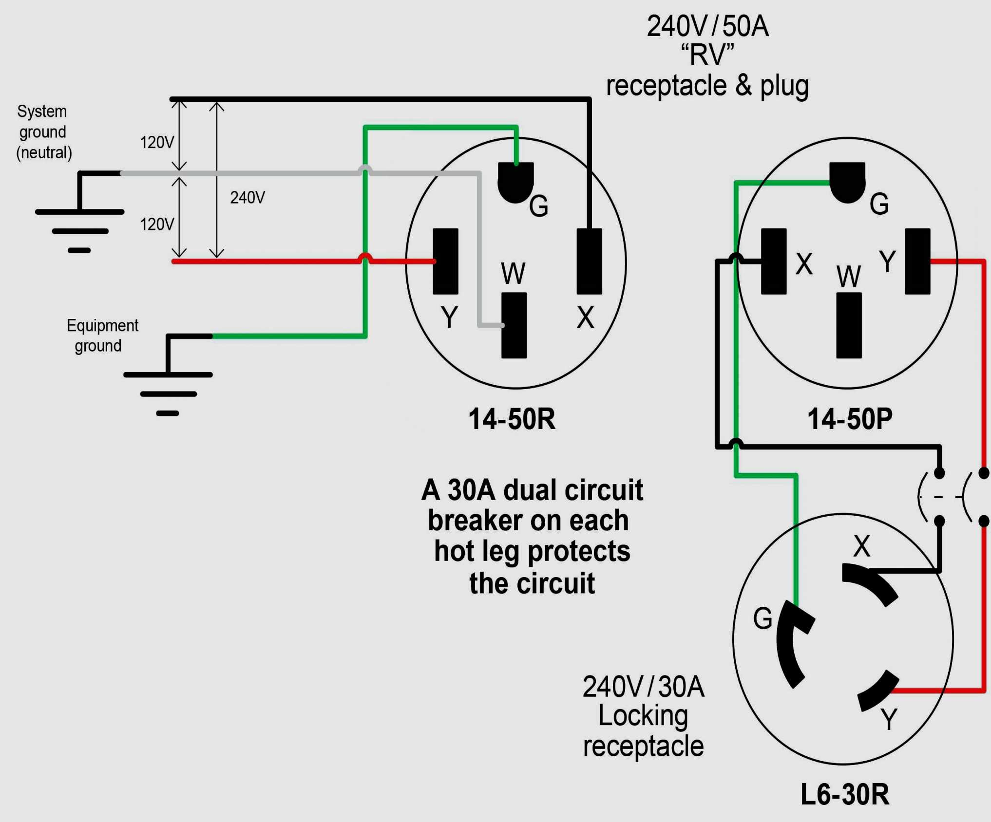
240v Receptacle Wiring Diagram Divaly Selecting the breaker: the first step in wiring a 240v circuit is selecting the appropriate breaker. a 240v breaker is double pole, meaning it has two separate circuits that combine to provide 240 volts of power. it is important to choose a breaker that matches the amperage rating of the circuit and the wiring. The following figure shows a typical breaker box panel for 120v and 240v circuits. there are three wires entering the main panel from the energy meter viz: hot 1 or line 1 = black color. hot 2 or line 2 = red color (for illustration purpose only) neutral = white color. click image to enlarge. Voltage between high leg and neutral = 1 2 x 220v x √3 = 208v (1 Φ). voltage between two hot phases = 120v x 2 = 240v (1 Φ). voltage between three phases = 240v (3 Φ). these are the general setup and may vary and depend on the installation e.g. neutral wire may be needed for three phase 240v outlets etc. A 120 240 volt circuit has two hots, a ground and a neutral wire, which allows the appliance to use both voltages. sensitive electronics, like touchpads and timers, run on 120 volts, heating elements and condensers on 240 volts. here i'll show you how to wire a 120 240v, 30 amp dryer outlet that accepts a four prong grounded plug.

Wiring Diagram 240v Outlet Voltage between high leg and neutral = 1 2 x 220v x √3 = 208v (1 Φ). voltage between two hot phases = 120v x 2 = 240v (1 Φ). voltage between three phases = 240v (3 Φ). these are the general setup and may vary and depend on the installation e.g. neutral wire may be needed for three phase 240v outlets etc. A 120 240 volt circuit has two hots, a ground and a neutral wire, which allows the appliance to use both voltages. sensitive electronics, like touchpads and timers, run on 120 volts, heating elements and condensers on 240 volts. here i'll show you how to wire a 120 240v, 30 amp dryer outlet that accepts a four prong grounded plug. 6. connect the wires: strip the insulation from the ends of the wires and connect them to the appropriate terminals on the circuit breaker and the 240v outlet. follow the wiring diagram provided with the outlet to ensure proper connections. use wire connectors to secure the wires in place. 7. This type of wiring diagram is commonly used for residential and small commercial applications. in a 240 volt single phase system, there are two hot wires, usually labeled as l1 and l2, and a neutral wire. these hot wires are each carrying 120 volts of electricity, but they are out of phase by 180 degrees, creating a total of 240 volts between.

Comments are closed.