3 Phase Capacitor Bank Wiring Diagram

3 Phase Capacitor Bank Wiring Diagram Greenist Using the lifting eyes on the capacitor bank frame, lift the capacitor bank, positioning it at the pole so that the bolts can slip into the slots on the capacitor bank pole mounting bracket. (figure 3) lower the capacitor bank onto the bolts. tighten the nuts on the bolts securely. 2. Excellent. the aim of project called „reactive power compensation panel” was to design capacitor bank with rated power of 200kvar and rated voltage of 400v adapted for operation with mains, where higher order harmonics are present. the capacitor bank was to be power capacitor based with automatic control by power factor regulator.

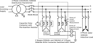
Capacitor Bank Working Symbol Calculation And Its Applications Types of 3 phase capacitor bank wiring diagrams. there are two primary wiring configurations for 3 phase capacitor banks: delta and wye (star). the choice of configuration depends on factors like voltage, current, and the specific requirements of the application. 1. delta connection. H connection can be used for delta or star single phase or three phase connections. the schematics below represents a branch between two phases or between phase and neutral. this type of wiring is intended for high power hv capacitor banks. for three phase capacitor banks, the unbalance is monitored on each phase. Installing a three phase capacitor bank can help to improve the power factor in electrical systems, making them more efficient by helping to reduce harmonics and improve voltage regulation. understanding how to properly install and wire a three phase capacitor bank circuit diagram is an important part of any electrical contractor's toolkit. The wiring diagram of the three phase capacitor bank is shown below. three phase capacitor bank wiring diagram as shown in the above figure, 2 capacitor banks have been connected to the grid.

3 Phase Capacitor Bank Wiring Diagram Installing a three phase capacitor bank can help to improve the power factor in electrical systems, making them more efficient by helping to reduce harmonics and improve voltage regulation. understanding how to properly install and wire a three phase capacitor bank circuit diagram is an important part of any electrical contractor's toolkit. The wiring diagram of the three phase capacitor bank is shown below. three phase capacitor bank wiring diagram as shown in the above figure, 2 capacitor banks have been connected to the grid. One of the essential things that must be taken into account after calculating the total and demand load of the project is to consider the power factor. inside the capacitor bank: power factor correction, circuits, calculation and schematics. but before indulging in the power factor correction, you should be aware of different types of loads. Heat dissipation and ample wire bending space. these capacitors are designed to be panel mounted. field wiring information below are typical wiring diagrams for the 3 phase kpc applied to the variable frequency drive (vfd) or motor. 3 phase and 1 phase, 600 volt class ul listed; file e 116124 kvar rated device ambient temperature: 40°c.
Diagram Wiring Diagram Panel Capacitor Bank Mydiagram Online One of the essential things that must be taken into account after calculating the total and demand load of the project is to consider the power factor. inside the capacitor bank: power factor correction, circuits, calculation and schematics. but before indulging in the power factor correction, you should be aware of different types of loads. Heat dissipation and ample wire bending space. these capacitors are designed to be panel mounted. field wiring information below are typical wiring diagrams for the 3 phase kpc applied to the variable frequency drive (vfd) or motor. 3 phase and 1 phase, 600 volt class ul listed; file e 116124 kvar rated device ambient temperature: 40°c.

Comments are closed.