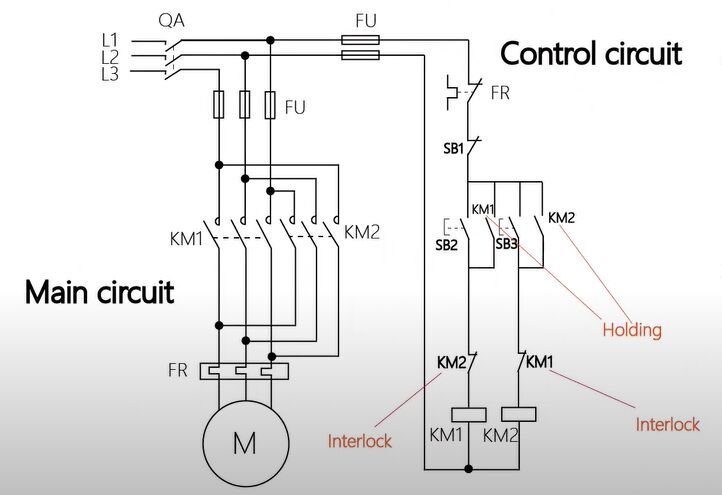
3 Phase Induction Motor Wiring Diagram

Wiring Diagram Star Delta Connection In 3 Phase Induction Motor A 3 phase motor is a type of motor that operates with three separate phases of electrical power, and its wiring diagram depicts the connections between these phases and the motor itself. the 3 phase wiring diagram for motors typically includes information such as the voltage and current ratings, the type of motor (e.g., induction motor or synchronous motor), and the connection details. To wire a 3 phase motor, first, identify the wires and check the wiring diagram on the motor. 6 wires are from the motor, 1 for grounding if provided, and 3 (l1 3) from the power supply. choose one of the two configurations (star or delta) and connect the wires to the terminals accordingly. then, connect the ground wire to the grounding.

3 Phase Induction Motor Circuit Diagram Wiring Diagram And The most common type of three phase motor is that which has nine labeled (and often colored) wires coming out of the box on the side. there are many motors with more or fewer wires, but nine is the most common. these nine wire motors may be internally connected with either a wye (star) or a delta configuration, established by the manufacturer. Three phase motor connection star delta without timer – power & control diagrams. three phase motor connection star delta (y Δ) reverse forward with – timer power & control diagram. starting & stopping of 3 phase motor from more than one place power & control diagrams. control 3 phase motor from more than two buttons – power & control. Working principle of 3 phase induction motor. the stator winding is overlapped at 120˚ (electrically) to each other. when a three phase supply is given to the stator winding, the rotating magnetic field (rmf) induced in the stator circuit. the speed of the rotating magnetic field is known as synchronous speed (ns). The three phase motor connection diagram typically consists of three sets of wires, labeled as “t1”, “t2”, and “t3”. these wires correspond to the three phases of the electrical system and are used to supply power to the motor. in addition to these three wires, there may also be other wires labeled with letters such as “u”, “v.

Comments are closed.