3 Phase Motor Starter Wiring Diagram Pdf

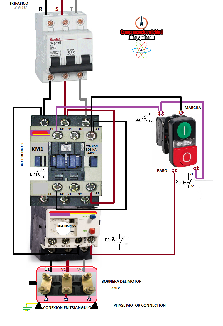
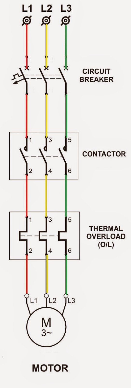
Dol Starter Wiring Diagram For 3 Phase Motor Controlling Is a typical wiring diagram for a three phase mag netic starter. figure 1. typical wiring diagram line diagrams show circuits of the operation of the controller. line diagrams, also called “schematic” or “elementary” dia grams, show the circuits which form the basic operation of the controller. they do not indicate the physical relation. The three main components of a 3 phase wiring diagram for motors are: power supply: the diagram shows the three phase power supply, typically labeled as l1, l2, and l3. these represent the three separate phases of the power source. motor: the diagram illustrates the motor as a single unit with labeled terminals.

Wiring 3 Phase Motor Starter If you don’t see what you’re looking for, please ask. springer controls has a certified ul508a panel shop to build custom starters and control panels up to 500v. for any custom options like hoa (hand off auto) starters, pilot lights, control transformers, or volume purchases, please contact us at 888 357 2138. Required when a two wire control device is used. the bulletin 595 auxiliary contacts are designed as “a” and “b” on the wiring diagram. these contacts are easily. added to any allen bradley bulletin 500 starter sizes 0 through 4. when this system is used, the phase connections on all of the starters must be the same. Working of direct online starter: the dol starter connects the 3 phase voltage supply i.e. r phase, y phase and b phase to the induction motor terminals. there are two types of circuits in the dol starter diagram given above; the control circuit and the power circuit. the control circuit:. Most motor starters consist of the contactor, an overload relay, and some type of manual or automated control circuit. the control is most likely either 120 vac or 24 vdc, but sometimes up to 230 vac and over 100 vdc. motor starter wiring diagram. one of the most common types of motor starters is a direct online or dol, motor starter.

Wiring Diagram For Motor Starter 3 Phase Working of direct online starter: the dol starter connects the 3 phase voltage supply i.e. r phase, y phase and b phase to the induction motor terminals. there are two types of circuits in the dol starter diagram given above; the control circuit and the power circuit. the control circuit:. Most motor starters consist of the contactor, an overload relay, and some type of manual or automated control circuit. the control is most likely either 120 vac or 24 vdc, but sometimes up to 230 vac and over 100 vdc. motor starter wiring diagram. one of the most common types of motor starters is a direct online or dol, motor starter. In this tutorial, we will demonstrate the automatic star delta (y Δ) starting method for 3 phase ac induction motors. this will include providing a schematic, power and control, plc ladder, and wiring diagrams. we will also explain how the star delta starter works and discuss its applications, as well as its advantages and disadvantages. The wiring of a 3 phase motor starter involves several key components, including a contactor, overload relays, and a control circuit. the contactor is responsible for establishing and interrupting the power supply to the motor, while the overload relays protect the motor from overheating by tripping the circuit in case of excessive current.

3 Phase Motor Starter Wiring Diagram Pdf In this tutorial, we will demonstrate the automatic star delta (y Δ) starting method for 3 phase ac induction motors. this will include providing a schematic, power and control, plc ladder, and wiring diagrams. we will also explain how the star delta starter works and discuss its applications, as well as its advantages and disadvantages. The wiring of a 3 phase motor starter involves several key components, including a contactor, overload relays, and a control circuit. the contactor is responsible for establishing and interrupting the power supply to the motor, while the overload relays protect the motor from overheating by tripping the circuit in case of excessive current.

Schematic 3 Phase Motor Starter Wiring Diagram Pdf

Comments are closed.