4 Pin Relay Wiring Diagram For Starter
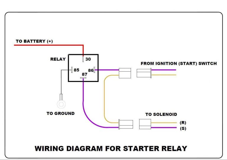
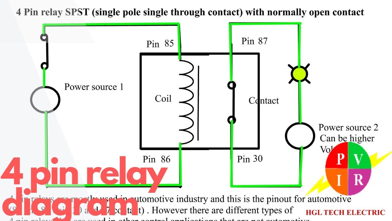
Simple 4 Pin Relay Diagram Dsmtuners The wiring diagram for a 4 pin relay used in a starter circuit typically involves connecting the control pins to the ignition switch or starter button. when the ignition switch or starter button is turned on, it sends a signal to the relay, closing the switch and allowing the current to flow through the starter motor. 4 pin relays have 4 pins emerging from a plastic casing: 87 – common contact for normally open or normally closed. 30 – power in for the electromagnet coil. 87a – normally closed contact. 85 – power out from electromagnet coil. inside there are spring loaded contacts connected to pins 87 and 87a. when at rest, 87a makes contact within.

4 Pin Starter Relay Wiring Diagram To wire a 4 pin relay, you need to connect the common pin to the power source, the normally open pin to the device you want to control, and the normally closed pin to the ground or earth. the control pin is connected to a switch or a control module that activates the relay. by using a 4 pin relay, you can safely control high current devices. Connect start relay to motor. to connect the start relay to the motor, follow these step by step instructions: identify the motor terminals: locate the motor’s terminals. these are usually labeled “s” (start), “r” (run), and “c” (common). the start terminal is where the start relay will be connected. A 4 pin relay is a commonly used type of relay that has four terminals or pins. understanding the pin diagram of a 4 pin relay is essential for proper installation and wiring. the pin diagram of a 4 pin relay typically includes four pins: input pin, output pin, common pin, and control pin. The main components of the 4 post starter relay diagram include the battery, starter motor, ignition switch, and the relay itself. the battery provides the initial power to start the engine, while the starter motor is responsible for physically cranking the engine. the ignition switch acts as the control point, allowing the driver to turn the.

1989 Ford F150 Starter Solenoid Wiring Diagram Wiring View And A 4 pin relay is a commonly used type of relay that has four terminals or pins. understanding the pin diagram of a 4 pin relay is essential for proper installation and wiring. the pin diagram of a 4 pin relay typically includes four pins: input pin, output pin, common pin, and control pin. The main components of the 4 post starter relay diagram include the battery, starter motor, ignition switch, and the relay itself. the battery provides the initial power to start the engine, while the starter motor is responsible for physically cranking the engine. the ignition switch acts as the control point, allowing the driver to turn the. The 4 pin relay wiring diagram starter is a must have for any car enthusiast. this diagram shows how to wire up the starter relay, providing the necessary power and connection points for starting the engine. it is essential for anyone planning to maintain or repair their vehicle, as a faulty wiring setup could lead to serious damage to the system. Step 3: identify the relay pins. before wiring the relay, you need to identify the different pins. a 4 pin relay typically has four pins labeled as follows: 85, 86, 87, and 30. pin 85 and 86 are used to control the relay, while pins 87 and 30 are used for the connection of the power source and the load.

Relay 4 Pin Wiring Diagram The 4 pin relay wiring diagram starter is a must have for any car enthusiast. this diagram shows how to wire up the starter relay, providing the necessary power and connection points for starting the engine. it is essential for anyone planning to maintain or repair their vehicle, as a faulty wiring setup could lead to serious damage to the system. Step 3: identify the relay pins. before wiring the relay, you need to identify the different pins. a 4 pin relay typically has four pins labeled as follows: 85, 86, 87, and 30. pin 85 and 86 are used to control the relay, while pins 87 and 30 are used for the connection of the power source and the load.

4 Pin Relay Wiring Diagram For Starter Econess

Comments are closed.