5 Wire Cdi Box Wiring Diagram

Diagram 5 Wire Cdi Diagram Mydiagram Online The 5 pin cdi box. the 5 pin cdi comes in the form of a black box, fitted with a male connector at the top. inside of this male connector, there are five different pins that connect to the various parts of the ignition system to provide power to the machine. these five pins connect the timing trigger pulse generator, ignition coil, ignition. On a 5 pin cdi system, you will find 5 different colored wires coming out of the cdi unit: green – connects to pickup coil signal input. white – connects to ac input from stator. red – main power source ( 12v from battery) black – main ground ( connection to battery) blue – output to ignition coil.

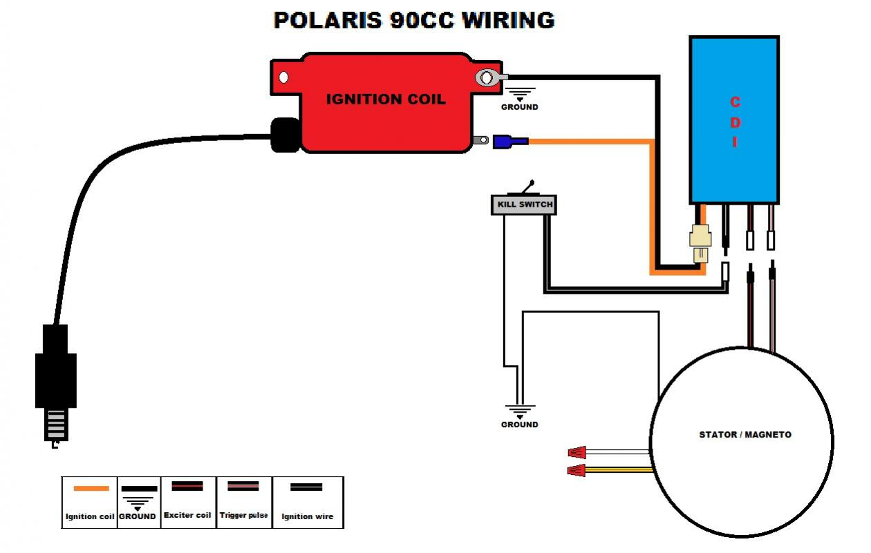
5 Wire Cdi Box Wiring Diagram Wiring a cdi involves connecting various wires and components, such as the stator, pickup coil, and ignition coil, in the correct sequence and configuration. this diagram shows you exactly how to wire a 5 pin cdi. each wire is labeled and color coded, making it easy to identify and connect the correct wires. Connecting chinese 5 pin cdi box. when purchasing a new cdi box, many times you can purchase a kit that also includes a new wiring harness along with it. but the chinese 5 pin cdi box should attach to the stock wiring harness in your vehicle as well. the wiring harness should have a female connector with five different wires that plugs into the. Looking to wire up your motorcycle cdi? in this video, we walk through a basic 5 pin cdi wiring diagram. we explain how each pin on the cdi unit connects and. The 5 wire cdi wiring diagram represents the connection between various components, including the ignition coil, stator, pick up coil, and the spark plug. each wire serves a specific purpose and understanding its function is key to diagnosing and resolving any potential issues.

Comments are closed.