7 Segment Counter Display Circuit Using Ic 555 And Cd4033 Wiring

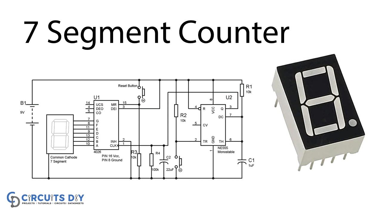
7 Segment Counter Using Ne555 And Cd4026 The ic 555 timer functions as the trigger for the counter, while the cd4033 is responsible for counting and incrementing the counts. it then sends the output values to the 7 segment display, which shows the numbers in a readable format. in operation, a user provides a high frequency signal to the ic 555 timer, which triggers the cd4033 4 bit. Counter circuits. timer ic 555. circuit above is used to display counts in 7 segment display.here we are employing two ics and 7 segment to perform this action. ic1 ne555, ic2 cd 4033 and a seven segment display lt543. as we know ic 555 is a timer ic and cd 4033 is a simple decoder ic which is commonly used to drive 7 segment displays.

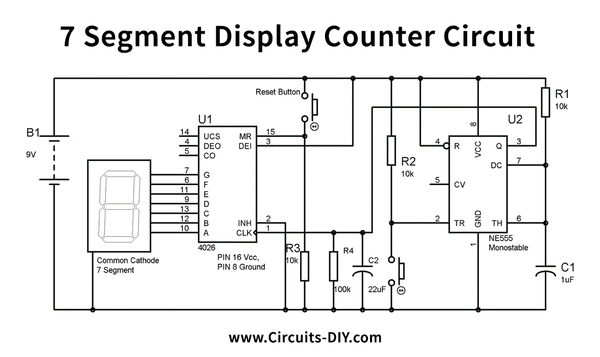
7 Segment Counter Display Circuit Using Ic 555 And Cd4033 Wiring View Ic cd4033 is a decade counter ic that functions and outputs numbers on 7 segment display lt543. the ic works such that each positive pulse at the input of the ic advances the output of the ic by count one. furthermore, a high reset signal clears the decade counter to its zero counts. It is a cmos seven segment counter ic and can be operated at very low power. it is a decade counter, counts in decimal digits (0 9). it is used to display numbers on seven segment displays and it increment the number by one, when a clock pulse is applied to its pin 1. means more the clock pulse rate, faster the numbers change in 7 segment display. Description. here is the circuit diagram of a seven segment counter based on the counter ic cd 4033. this circuit can be used in conjunction with various circuits where a counter to display the progress adds some more attraction. in this circuit a 7 segment display is connected with two ne555 ic’s and cd4033 ic to display counts from 0 to 9. Fig. 2: pin configration of 7 segment display. 3. interfacing cd4033 with the timer ic. in the following circuit we have used a 555 timer in astable oscillator mode to provide clock signal to input of ic cd4033 to start its counting which can be display on 7 segment display. here reset switch is used to reset the counting any time needed by the.

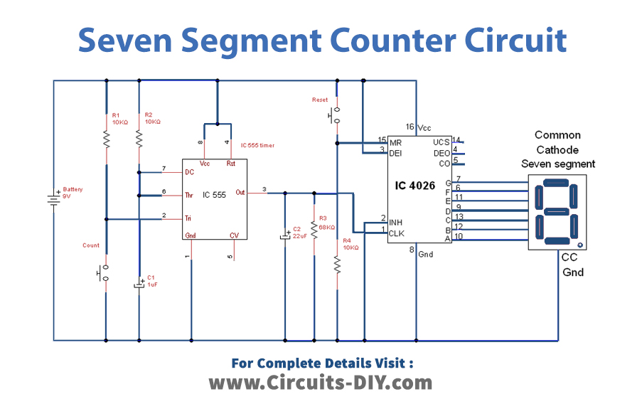
3 Digit Counter Circuit Diagram Description. here is the circuit diagram of a seven segment counter based on the counter ic cd 4033. this circuit can be used in conjunction with various circuits where a counter to display the progress adds some more attraction. in this circuit a 7 segment display is connected with two ne555 ic’s and cd4033 ic to display counts from 0 to 9. Fig. 2: pin configration of 7 segment display. 3. interfacing cd4033 with the timer ic. in the following circuit we have used a 555 timer in astable oscillator mode to provide clock signal to input of ic cd4033 to start its counting which can be display on 7 segment display. here reset switch is used to reset the counting any time needed by the. Circuit explanation: in the 555 timer pin 2,6 and 7 are shorted and connected to the capacitor c1. pin 4 and 8 are connected to vcc. pin 3 is the output pin. in the case of cd4033 ic pin 1 is the clock input. pin 15 is the reset pin, by applying vcc you can reset the count to 0. pin 6,7,9,10,11,12,13 are given to the seven segment display. Interfacing cd4033 ic with common cathode 7 segment display. cd4033 is a decoder ic, which is commonly used to drive 7 segment displays. the pin 1 of cd 4033 ic is used as carry in, which is highly sensitive to electromagnetic radiations and the pin 5 of this ic is used for carry out to the next stage. figure shows the interfacing diagram of cd.

Simple Seven Segment Counter Circuit Using Cd4026 Circuit explanation: in the 555 timer pin 2,6 and 7 are shorted and connected to the capacitor c1. pin 4 and 8 are connected to vcc. pin 3 is the output pin. in the case of cd4033 ic pin 1 is the clock input. pin 15 is the reset pin, by applying vcc you can reset the count to 0. pin 6,7,9,10,11,12,13 are given to the seven segment display. Interfacing cd4033 ic with common cathode 7 segment display. cd4033 is a decoder ic, which is commonly used to drive 7 segment displays. the pin 1 of cd 4033 ic is used as carry in, which is highly sensitive to electromagnetic radiations and the pin 5 of this ic is used for carry out to the next stage. figure shows the interfacing diagram of cd.

7 Segment Led Counter Circuit Diagram

Comments are closed.