74hc595 74hc165 Shift Registers With Arduino

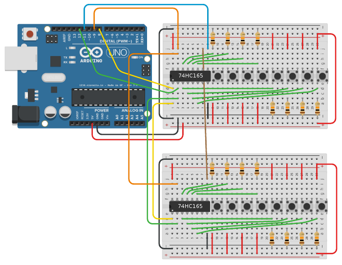
Arduino 74hc595 Shift Register Projects Shift registers 74hc595 & 74hc165 with arduino. description. learn to use the 74hc595 and 74hc165 shift registers to add extra input and output ports to your arduino. we will see how these simple devices work and how to use them to build a fancy led light display with eight different flashing patterns. author. The 74hc165 is an 8 bit parallel in serial out (piso) shift register. you can use piso to read the status of 8 pins using only three pins on the arduino uno. the shift register 74hc165 is used to increase the number of input pins for arduino. the ic can be cascaded to scale the number of inputs without a further increase in the control pins.

Ic 74hc165 Shift Register Input 8 Bit Expand your arduino with shift registers! today i will show you how to use the 74hc595 and 74hc165 to increase your arduino's inputs and outputs so we can fl. At sometime or another you may run out of pins on your arduino board and need to extend it with shift registers. hope this helps! captainobvious, the 74hc165 is a parallel to serial device while the 74hc595 is a serial to parallel device. the have opposite purposes. the 165 is used for inputs, not to control outputs. The solution is to use a ‘shift register,’ which allows you to add more i o pins to the arduino (or any microcontroller). by far the most widely used shift register is the 74hc595, also known as just “595”. the 74hc595 controls eight different output pins with only three input pins. if you need more than 8 i o pins, you can daisychain. Here is a breakdown of this extensive coverage of shift registers with the arduino: 00:00 introduction 03:03 how shift registers work 07:32 more outputs with the 74hc595 15:22 driving a 7 segment display 21:49 extra inputs with the 74hc165 29:46 74hc595 & 74hc165 together 34:30 custom light sequencer.

Shift Registers 74hc595 74hc165 With Arduino The solution is to use a ‘shift register,’ which allows you to add more i o pins to the arduino (or any microcontroller). by far the most widely used shift register is the 74hc595, also known as just “595”. the 74hc595 controls eight different output pins with only three input pins. if you need more than 8 i o pins, you can daisychain. Here is a breakdown of this extensive coverage of shift registers with the arduino: 00:00 introduction 03:03 how shift registers work 07:32 more outputs with the 74hc595 15:22 driving a 7 segment display 21:49 extra inputs with the 74hc165 29:46 74hc595 & 74hc165 together 34:30 custom light sequencer. Part 1 – the 74hc595 described how to add digital outputs using the 74hc595 8 bit serial in parallel out (sipo) shift register ic. part 2 – the 74hc165 (currently reading) describes how to add digital inputs using the 74hc165 8 bit parallel in serial out (piso) shift register ic. part 3 – the mcp23017 will describe how to add both digital. At the time of each pulse, if the data pin is high, then a 1 gets pushed into the shift register. otherwise, it is a 0. when all eight pulses have been received, then enabling the 'latch' pin copies those eight values to the latch register. this is necessary, otherwise the wrong leds would flicker as the data was being loaded into the shift.

Expand Your Arduino With Shift Registers Today I Will Show You How To Part 1 – the 74hc595 described how to add digital outputs using the 74hc595 8 bit serial in parallel out (sipo) shift register ic. part 2 – the 74hc165 (currently reading) describes how to add digital inputs using the 74hc165 8 bit parallel in serial out (piso) shift register ic. part 3 – the mcp23017 will describe how to add both digital. At the time of each pulse, if the data pin is high, then a 1 gets pushed into the shift register. otherwise, it is a 0. when all eight pulses have been received, then enabling the 'latch' pin copies those eight values to the latch register. this is necessary, otherwise the wrong leds would flicker as the data was being loaded into the shift.

Comments are closed.