8085 Pin Diagram In Microprocessor Use My Notes

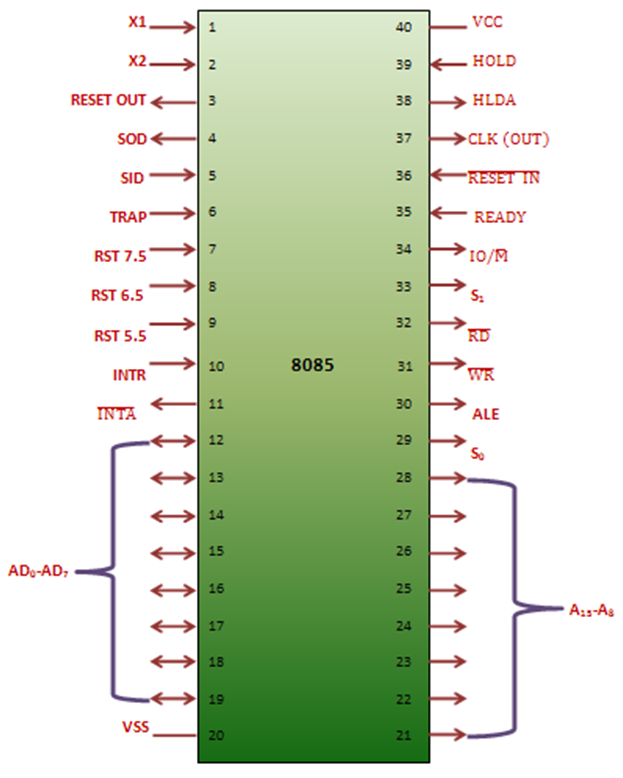
Pin Diagram Of 8085 Microprocessor Usemynotes Pin diagram of 8085 microprocessor is as given below: 1. address bus and data bus: the address bus is a group of sixteen lines i.e a0 a15. the address bus is unidirectional, i.e., bits flow in one direction from the microprocessor unit to the peripheral devices and uses the high order address bus. 2. Sid and sod. this is the 30th pin in the 8085 pin diagram in microprocessor. these two pins are used for serial data communication. in the serial input data, the information is uploaded into the 7th bit of the accumulator while rim instruction is performed. rim (read interrupt mask) verifies whether the interrupt is covered or not covered.

Pin Diagram Of 8085 8085 Microprocessor Course The 8085 microprocessor is an 8 bit microprocessor. it consists of a 40 pin i.c. package and is fabricated on a single lsi chip. the intel 8085 only uses a single 5v dc supply for its operation. the clock speed of the microprocessor is about 3mhz and the clock cycle is 320 ns. the time for the clock cycle of intel 8085ah 2, the version is 200 ns. Reset in − this signal is used to reset the microprocessor by setting the program counter to zero. reset out − this signal is used to reset all the connected devices when the microprocessor is reset. ready − this signal indicates that the device is ready to send or receive data. if ready is low, then the cpu has to wait for ready to go high. The figure below shows the pin diagram of 8085 showing 40 pin configuration: the signals of this 40 pin ic is grouped into 7 categories, which are given below: power supply and clock signals. data bus. address bus. serial i o ports. control and status signals. interrupts and externally generated signals. Pin diagram of 8085 microprocessor. 40 pins are arranged in seven categories on the 8085 microprocessor’s pin diagram: the address bus, the data bus, the control signals and status signals, the power supply and frequency, the reset signals, the dma signals, and the serial input output ports. these pins serve specific functions and play a.

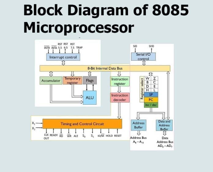
The Block Diagram Of 8085 Microprocessor Usemynotes The figure below shows the pin diagram of 8085 showing 40 pin configuration: the signals of this 40 pin ic is grouped into 7 categories, which are given below: power supply and clock signals. data bus. address bus. serial i o ports. control and status signals. interrupts and externally generated signals. Pin diagram of 8085 microprocessor. 40 pins are arranged in seven categories on the 8085 microprocessor’s pin diagram: the address bus, the data bus, the control signals and status signals, the power supply and frequency, the reset signals, the dma signals, and the serial input output ports. these pins serve specific functions and play a. Interrupt signals: the 8085 pin diagram has five hardware interrupt signals : rst 5.5, rst 6.5, rst 7.5, trap and intr. the microprocessor recognises interrupt requests on these lines at the end of the current instruction execution. the inta (interrupt acknowledge) signal is used to indicate that the processor has acknowledged an intr interrupt. The 8085 microprocessor is an 8 bit microprocessor that was developed by intel in the mid 1970s. it was widely used in the early days of personal computing and was a popular choice for hobbyists and enthusiasts due to its simplicity and ease of use. the architecture of the 8085 microprocessor consists of several key components, including the.

Comments are closed.