Adc0808 Simple Analoque To Digital Converter Schematic Design

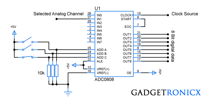
Adc0808 Simple Analoque To Digital Converter Schematic Design Ic adc0808: this ic was a simple analog to digital converter which provides a resulting 8 bit data for input analog signal. the pins out1 to out8 gives the output data bits in binary form whereas in0 to in7 allows user to feed their analog signal. user can use only one input channel at a time and the channel selection was done by using the pins. The circuit of analogue to digital converter shown here is configured around adc0808, getting rid of the utilization of a microprocessor. the adc0808 is definitely an 8 bit a d converter, that has data output lines d0 d7. it operates on the principle of successive approximation. it features a total of eight analogue input channels, out of which.

Analog To Digital Converter Circuit Using Adc0808 Casinodigitaltech Adc0808 – simple analoque to digital converter. the adc0808 ic needs clock signal of normally 550 khz, which can be simply produced from an astable multivibrator constructed applying 7404 inverter gates. in order to visualise the digital output, the row of eight leds (led1 through led8) have been utilized, wherein every single led is. The adc0808, adc0809 data acquisition component is a monolithic cmos device with an 8 bit analog to digital converter, 8 channel multiplexer and microprocessor compatible control logic. the 8 bit a d converter uses successive approximation as the conversion technique. the converter features a high impedance chopper stabilized comparator, a 256r. For example a 4 bit adc will have a resolution of one part in 15, (2 4 – 1) whereas an 8 bit adc will have a resolution of one part in 255, (2 8 – 1). thus an analogue to digital converter takes an unknown continuous analogue signal and converts it into an “n” bit binary number of 2 n bits. Circuit description: circuit of “interfacing adc0808 with 8051” is little complex which contains more connecting wire for connecting device to each other. in this circuit we have mainly used at89s52 as 8051 microcontroller, adc0808, potentiometer and lcd. a 16x2 lcd is connected with 89s52 microcontroller in 4 bit mode.

Adc0808 Simple Analoque To Digital Converter Schematic Design For example a 4 bit adc will have a resolution of one part in 15, (2 4 – 1) whereas an 8 bit adc will have a resolution of one part in 255, (2 8 – 1). thus an analogue to digital converter takes an unknown continuous analogue signal and converts it into an “n” bit binary number of 2 n bits. Circuit description: circuit of “interfacing adc0808 with 8051” is little complex which contains more connecting wire for connecting device to each other. in this circuit we have mainly used at89s52 as 8051 microcontroller, adc0808, potentiometer and lcd. a 16x2 lcd is connected with 89s52 microcontroller in 4 bit mode. Adc0808 interfacing tutorial. adc0808 adc0809 is an 8 channel 8 bit analog to digital converter. unlike adc0804 which has one analog channel, this adc has 8 multiplexed analog input channels. this tutorial will provide you basic information regarding this adc, testing in free run mode and interfacing example with 8051 with sample program in c. The adc0808 adc0809 is an 8 bit adc that also contains an 8 channel multiplexer. the fpga used in this case was the altera 10k20rc240 4 that is found on the up 1 boards used in the course. the purpose of this documentation is to first introduce users to the adc0808 adc0809, then to outline how to connect external circuitry to the adc, and then.

Adc0808 Simple Analoque To Digital Converter Schematic Design Adc0808 interfacing tutorial. adc0808 adc0809 is an 8 channel 8 bit analog to digital converter. unlike adc0804 which has one analog channel, this adc has 8 multiplexed analog input channels. this tutorial will provide you basic information regarding this adc, testing in free run mode and interfacing example with 8051 with sample program in c. The adc0808 adc0809 is an 8 bit adc that also contains an 8 channel multiplexer. the fpga used in this case was the altera 10k20rc240 4 that is found on the up 1 boards used in the course. the purpose of this documentation is to first introduce users to the adc0808 adc0809, then to outline how to connect external circuitry to the adc, and then.

Analog To Digital Converter Schematic

Comments are closed.