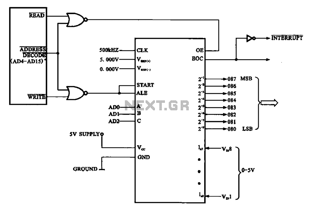
Adc0809 Circuit Diagram

Adc0809 Circuit Diagram The adc0808, adc0809 data acquisition component is a monolithic cmos device with an 8 bit analog to digital converter, 8 channel multiplexer and microprocessor compatible control logic. the 8 bit a d converter uses successive approximation as the conversion technique. the converter features a high impedance chopper stabilized comparator, a 256r. Adc0808 interfacing tutorial. adc0808 adc0809 is an 8 channel 8 bit analog to digital converter. unlike adc0804 which has one analog channel, this adc has 8 multiplexed analog input channels. this tutorial will provide you basic information regarding this adc, testing in free run mode and interfacing example with 8051 with sample program in c.

Adc0809 Circuit Diagram These circuits are implemented using a standard metal gatecmos process. this process is particularly suitable to applications where both analog and digital functions must be implemented on the same chip. these two converters, the adc0808 and adc0809, are functionally identical except that the adc0808. Adc0808 adc0809 8 bit µp compatible a d converters with 8 channel analog multiplexer introduction the adc0808 adc0809 data acquisition devices (dad) implement on a single chip most the elements of the stan dard data acquisition system. they contain an 8 bit a d converter, 8 channel multiplexer with an address input latch, and associated. In the above circuit i have used a potentiometer to feed in a variable voltage of 0v to 5v to the in1 pin and the present voltage is read using a voltmeter. to read the voltage from channel one we have to set a=1 and b=0 and c=0 according to the table below, this can be done using a i o pin of a mpu mcu. 1 features. 1• compatible with 8080 μp derivatives – no interfacing logic needed – access time 135 ns. easy interface to all microprocessors, or operates as a stand alone deivce. differential analog voltage inputs. logic inputs and outputs meet both mos and ttl voltage level specifications.

Comments are closed.