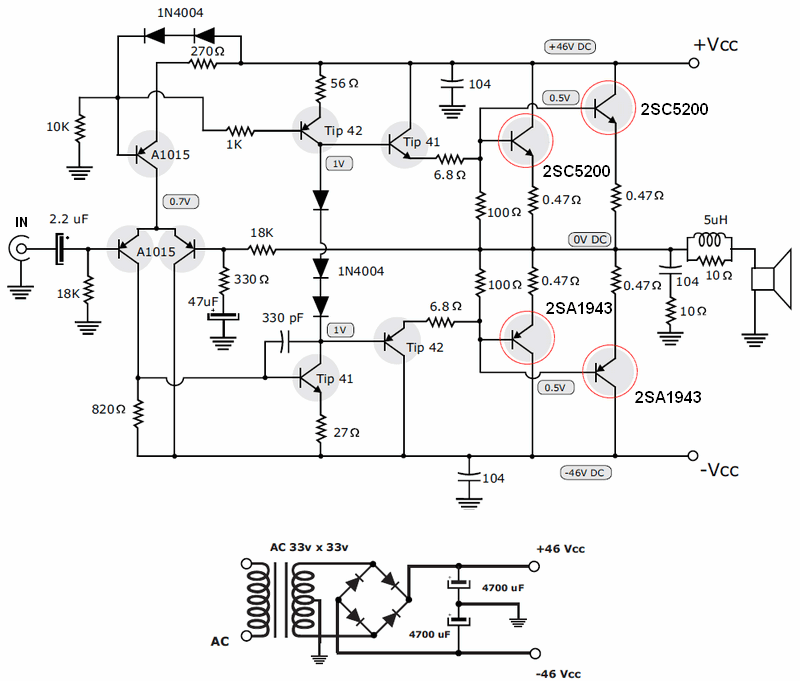
Amplifier Circuit Diagram Using 2sc5200 And 2sa1943 Electronics Help C

2sa1943 2sc5200 200w Amplifier Circuit вђ Electronics Projects Circuit 2sc5200 2sa1943 amplifier circuit diagram. akhil satheesh. july 5, 2024. 2sc5200 2sa1943 audio amplifier produces a high power output. the output watts is around 200 at 4 ohms load of impedance. the 2sc 5200 and 2sa 1943 are new generation audio power amplifier transistors. nowadays the audio power amplifier such as subwoofer audio amplifier. The power transistors of the 200w afi circuit do not require the classic 2sc5200 and 2sa1943 quiescent current adjustment. the amplifier can deliver 100w rms power with a 4 ohm speaker and a 200w rms 8 ohm speaker. amplifier operating voltage max. 2x50v dc 6a (2x33vac or 2x36vac transformers can be used) supply filter capacitors for usable.

2sc5200 Pinout вђ Ayu Belajar We used 2sc5200 and 2sa1943. 2sc5200 is an npn transistor and 2sa1943 is a pnp transistor. we can use a maximum of 230 volts and 1.5 amperes. but here in this circuit diagram, we can use a maximum of 50 voltage. the voltage depends on various circuits. this circuit is for a maximum of 50 voltage. About press copyright contact us creators advertise developers terms privacy policy & safety how works test new features nfl sunday ticket press copyright. Facebook electronicshelpcare facebook diplomaineee pinterest electrohelpcare pins pinterest ele. The circuit diagram for an amplifier using the 2sc5200 and 2sa1943 transistors typically consists of a voltage amplifier stage, a driver stage, and an output stage. the voltage amplifier stage helps boost the incoming audio signal to a suitable level for the driver stage. the driver stage further amplifies the signal and provides the necessary.

200w Amplifier Circuit Using 2sc5200 2sa1943 Tronicspro Facebook electronicshelpcare facebook diplomaineee pinterest electrohelpcare pins pinterest ele. The circuit diagram for an amplifier using the 2sc5200 and 2sa1943 transistors typically consists of a voltage amplifier stage, a driver stage, and an output stage. the voltage amplifier stage helps boost the incoming audio signal to a suitable level for the driver stage. the driver stage further amplifies the signal and provides the necessary. The 1000w amplifier circuit diagram presented in this article is a powerful audio solution that incorporates five pairs of 2sc5200 and 2sa1943 transistors in the output section, tip41, tip42, b560, and d438 transistors in the driver section, and three c1845 transistors in the preamplifier stage. this well designed circuit ensures exceptional. The 1000w power amplifier circuit schematic utilizing the 2sc5200 and 2sa1943 transistors is a robust design capable of delivering high quality audio output. this amplifier operates on a ±45v to 75v dc power supply and employs a complementary pair of transistors for each channel. the circuit diagram ensures the accurate reproduction of sound.

1000w Amplifier Circuit Using 2sc5200 2sa1943 Tronicspro The 1000w amplifier circuit diagram presented in this article is a powerful audio solution that incorporates five pairs of 2sc5200 and 2sa1943 transistors in the output section, tip41, tip42, b560, and d438 transistors in the driver section, and three c1845 transistors in the preamplifier stage. this well designed circuit ensures exceptional. The 1000w power amplifier circuit schematic utilizing the 2sc5200 and 2sa1943 transistors is a robust design capable of delivering high quality audio output. this amplifier operates on a ±45v to 75v dc power supply and employs a complementary pair of transistors for each channel. the circuit diagram ensures the accurate reproduction of sound.

Comments are closed.