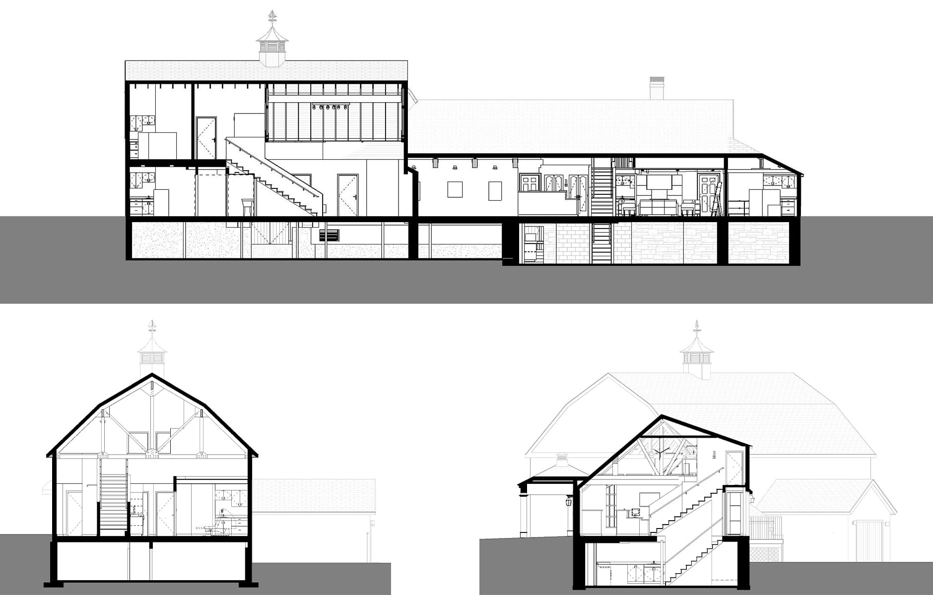
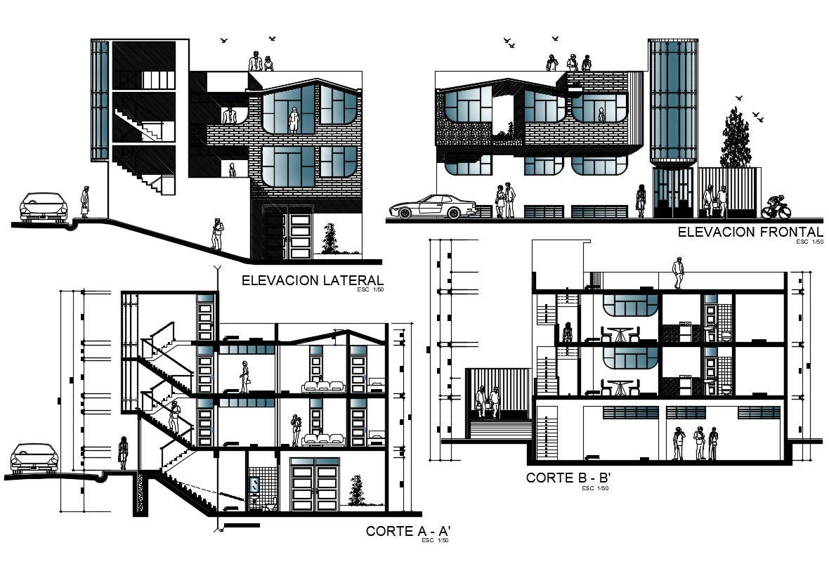
Architectural Linework On Plans Elevations And Section

House Elevation Drawing Planning Drawings Jhmrad 21734 How to present floor plans elevations and sections in ink. the process of drawing on trace paper. how to layout your work and present a clear drawing. Plan, section, and elevation are different types of drawings used by architects to graphically represent a building design and construction. a plan drawing is a drawing on a horizontal plane showing a view from above. an elevation drawing is drawn on a vertical plane showing a vertical depiction. a section drawing is also a vertical depiction.

Why Are Architectural Sections Important To Projects Patriquin In architecture, drawings are key throughout the design process. they include plan views to outline spaces, section views to show forms, and elevation views for clear depictions. these drawings are crucial for creativity, influencing both our homes and daily lives. for those in construction, knowing how to use these drawings can turn a basic. We use architectural line weights slightly differently in each drawing. but let’s start with plan, section and elevation and refer to line weights as thickest to thinnest. section and cut plan – thickest for the section through the ground line. thick for the cut through primary elements such as walls, floor and roof. In a standard set of architectural plans on a small residential project, the elevations will most likely be a set of drawings from the main facades of the building. for example, front, back and two sides – or north, south, east and west. the sections would most likely be two or more sections cut at 90 degrees of one another to give. That’s a “plan” view. in both cases, the solid lines indicate the boundaries of what you are looking at. solid single line. in a plan view, a solid single line is usually something like the edge of a cabinet, a floor threshold, the nosing of a stair, or the edge of a tabletop. it isn’t a wall (read more about what walls look like below).

Apartment Section Plan And Elevation Design Cadbull In a standard set of architectural plans on a small residential project, the elevations will most likely be a set of drawings from the main facades of the building. for example, front, back and two sides – or north, south, east and west. the sections would most likely be two or more sections cut at 90 degrees of one another to give. That’s a “plan” view. in both cases, the solid lines indicate the boundaries of what you are looking at. solid single line. in a plan view, a solid single line is usually something like the edge of a cabinet, a floor threshold, the nosing of a stair, or the edge of a tabletop. it isn’t a wall (read more about what walls look like below). Elevation. an elevation is a drawing to scale showing a view of a building as seen from one side a fl at representation of one façade. this is the most common view used to describe the external appearance of a building. each elevation is labelled in relation to the compass direction it faces, e.g. looking toward the north you would be seeing. Sections and elevations are always drawn with the ground plane cut through in section. elements cut in plan and section (ie. wall type and thickness, doors, windows) should be drawn the same way, as they are representing the same thing. internal elevation information is secondary in sections and should generally be indicative.

A Drawing Of A Floor Plan Is Shown Elevation. an elevation is a drawing to scale showing a view of a building as seen from one side a fl at representation of one façade. this is the most common view used to describe the external appearance of a building. each elevation is labelled in relation to the compass direction it faces, e.g. looking toward the north you would be seeing. Sections and elevations are always drawn with the ground plane cut through in section. elements cut in plan and section (ie. wall type and thickness, doors, windows) should be drawn the same way, as they are representing the same thing. internal elevation information is secondary in sections and should generally be indicative.

Comments are closed.