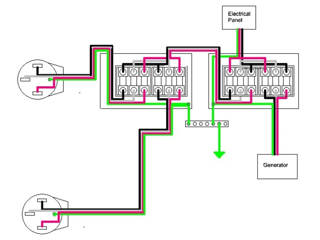
Ati Transfer Switch Wiring Diagram

Ati Transfer Switch Wiring Diagram Ati 400 a ati 630 a ati 800 a ati 1000 a ati 1250 a ati 1600 a. save pdf. view and download socomec ati 250 a technical instruction manual online. transfer panel. ati 250 a control panel pdf manual download. also for: ati 400 a, ati 630 a, ati 800 a, ati 1000 a, ati 1250 a, ati 1600 a. The bypass isolation ats control wiring diagram includes connections for the utility power, backup generators, bypass switch, load, and various control circuits for automatic transfer, bypass operation, and alarm monitoring. these are just a few of the main categories of automatic transfer switch control wiring diagrams.

Ati Transfer Switch Wiring Diagram 3 wire kits (those without a neutral) do not include for the power supply to terminals (101 102 and 201 – 202). ensure that you have ordered the correct reference prior to installation. (refer to the accessory section for details). source source atys t 541995c socomec page 46: sensing kit wiring diagram. Owner's manual automatic transfer switch. An auto transfer switch (ats) is an essential component of a backup power system. it is designed to automatically switch the power source from the main power grid to a backup generator in the event of a power outage. the wiring diagram of an ats illustrates how the various components are connected to ensure a smooth and reliable transfer. Wiring 120v & 240, 1 phase manual transfer switch – nec. the following wiring diagram in fig 3 shows the reliance manual transfer switch connected to the main 120 240 v panel and a portable generator. step by step guide is posted before in the post under the title wiring a portable generator using manual transfer switch for 120 & 240v.

Ati Transfer Switch Wiring Diagram An auto transfer switch (ats) is an essential component of a backup power system. it is designed to automatically switch the power source from the main power grid to a backup generator in the event of a power outage. the wiring diagram of an ats illustrates how the various components are connected to ensure a smooth and reliable transfer. Wiring 120v & 240, 1 phase manual transfer switch – nec. the following wiring diagram in fig 3 shows the reliance manual transfer switch connected to the main 120 240 v panel and a portable generator. step by step guide is posted before in the post under the title wiring a portable generator using manual transfer switch for 120 & 240v. Here are the steps (8 in total) [silver cymbal]: step 1: attach a nail or screw to the transfer switch casing. step 2: mount the transfer switch casing. step 3: screw the casing to the wall securely. step 4: insert the transfer switch. step 5: secure the transfer switch to its casing. Providing 24 hour automatic control of standby generator sets, 365 days a year. a load transfer panel is a panel that is wired into the premises electrical distribution system to allow a generator to be used. it prevents the generator from back feeding into the mains power supply which could cause serious injury to line workers trying to.

Comments are closed.