Atv Cdi Wiring Diagrams

Diagram Yamaha Atv Cdi Wiring Diagrams Mydiagram Online The 6 pin cdi comes in the form of a black box fitted with a male connector up top. there are six different electrical pins inside of this connector that serve to provide power to the machine by syncing the various parts of the ignition system. these six pins connect the ignition power to the cdi, the ignition coil, the timing trigger or pulse. Checking ignition coil resistance. step 1: remove the coil from the vehicle. step 2: set multimeter to ohms mode step 3: touch the positive and negative meter leads to the coil’s primary terminals step 4: check meter readout – should be 1.1 to 1.6 ohm on most chinese bikes.

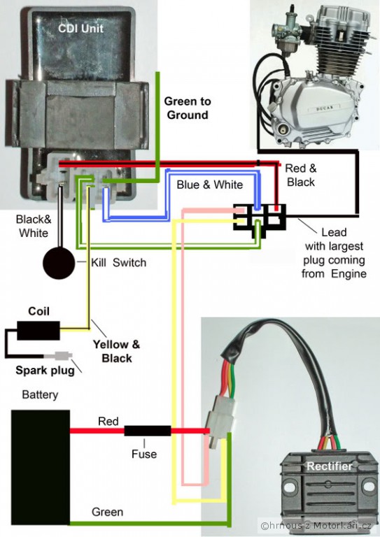
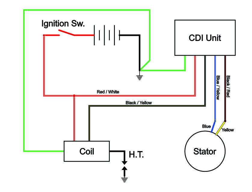
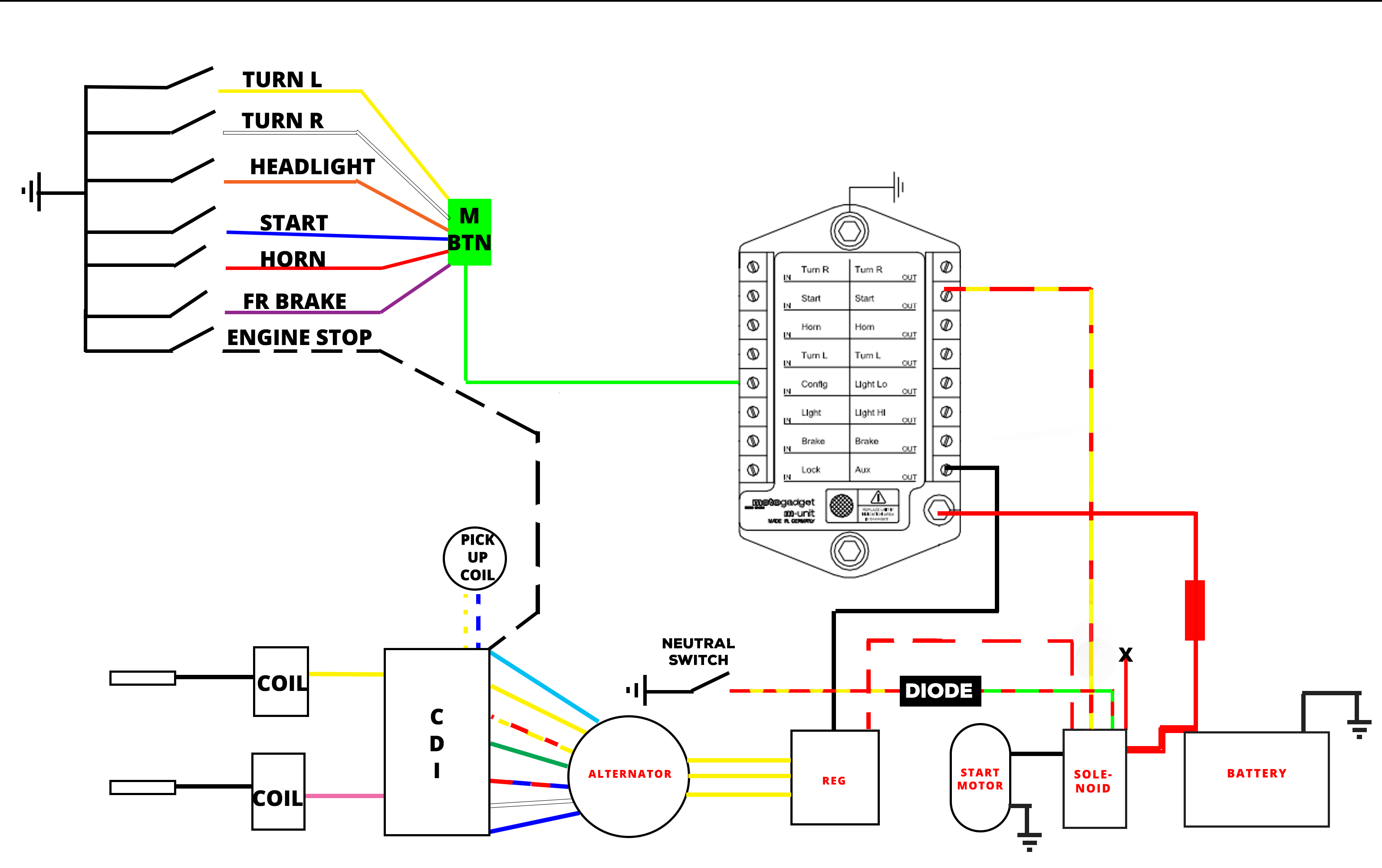
Atv Cdi Box Wiring Diagram Four Wire 125cc Wiring Diagram When it comes to the wiring diagram of a cdi (capacitor discharge ignition) box in an atv (all terrain vehicle), it is important to understand the different connections involved. the cdi box is a crucial component responsible for regulating the ignition system and delivering high voltage sparks to the spark plugs. The 6 wires of a cdi connect the power, pickup trigger, ground, and ignition coil. trace each wire in the wiring diagram during troubleshooting. use a multimeter to test trigger, power, ground, and coil connections. know the spark generation sequence including signal trigger, amplification, energy storage and discharge. The 5 pins on the cdi connector supply power, ground, and signals to control this process. here is a quick overview of each pin’s function: pin 1 – ground. pin 2 – 12vdc from battery via ignition switch and fuses. pin 3 – trigger signal from ac generator stator. pin 4 – switched 12vdc to ignition coil. The wiring diagram typically includes different symbols to represent each component and lines to show the connections between them. some common symbols used in a chinese atv cdi box wiring diagram include a circle for the cdi box, a line for the ignition coil, and a triangle for the kill switch.

Diagram Dc Cdi Atv Wiring Diagrams Mydiagram Online The 5 pins on the cdi connector supply power, ground, and signals to control this process. here is a quick overview of each pin’s function: pin 1 – ground. pin 2 – 12vdc from battery via ignition switch and fuses. pin 3 – trigger signal from ac generator stator. pin 4 – switched 12vdc to ignition coil. The wiring diagram typically includes different symbols to represent each component and lines to show the connections between them. some common symbols used in a chinese atv cdi box wiring diagram include a circle for the cdi box, a line for the ignition coil, and a triangle for the kill switch. Most polaris atv and utv models use a dc cdi box. the dc cdi box relies on the vehicle’s 12 volt battery for power via direct current. if you own an electric start polaris model manufactured in the last 15 years or so, you can be pretty sure its cdi box is of the dc variety. but some older polaris models do use an ac cdi box. On a 5 pin cdi system, you will find 5 different colored wires coming out of the cdi unit: green – connects to pickup coil signal input. white – connects to ac input from stator. red – main power source ( 12v from battery) black – main ground ( connection to battery) blue – output to ignition coil.

Atv Cdi Box Wiring Most polaris atv and utv models use a dc cdi box. the dc cdi box relies on the vehicle’s 12 volt battery for power via direct current. if you own an electric start polaris model manufactured in the last 15 years or so, you can be pretty sure its cdi box is of the dc variety. but some older polaris models do use an ac cdi box. On a 5 pin cdi system, you will find 5 different colored wires coming out of the cdi unit: green – connects to pickup coil signal input. white – connects to ac input from stator. red – main power source ( 12v from battery) black – main ground ( connection to battery) blue – output to ignition coil.

Comments are closed.