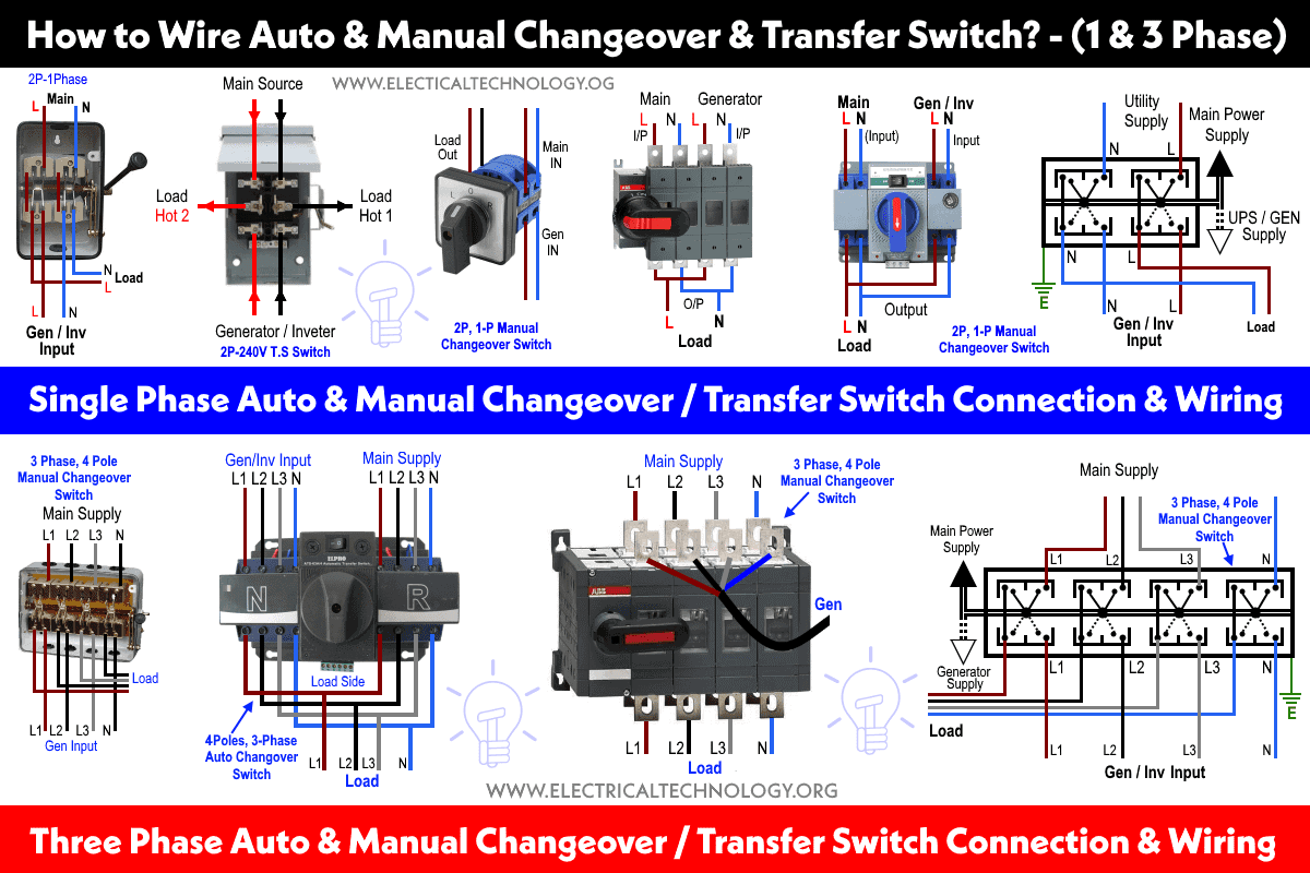
Auto Changeover Switch Wiring Diagram

Automatic Changeover Switch Wiring Diagram Wiring 120v & 240, 1 phase manual transfer switch – nec. the following wiring diagram in fig 3 shows the reliance manual transfer switch connected to the main 120 240 v panel and a portable generator. step by step guide is posted before in the post under the title wiring a portable generator using manual transfer switch for 120 & 240v. Use electrical cables to connect the line input of the switch to the utility power supply. ensure that the connections are secure and use wire connectors to join the cables together. 4. connect the backup power source. next, connect the backup power source, such as a generator, to the automatic changeover switch.

Automatic Changeover Switch Schematic Diagram Learn how to wire an automatic changeover switch for single phase power supply with this detailed video tutorial. suitable for beginners and experts. 3. familiarize yourself with the switch’s wiring diagram: it is essential to refer to the wiring diagram provided with the changeover switch. this diagram will show the various terminals and connections that need to be made. understanding the diagram beforehand will ensure a smoother and more accurate wiring process. 4. Follow the wiring diagram to properly connect the wires from the power sources to the corresponding terminals on the switch. step 4: connect the load. the load refers to the electrical equipment or appliances that you want to switch between the two power sources. again, refer to the wiring diagram to connect the load wires to the appropriate. This video i will show you automatic changeover switch wiring diagram single phase with main supply & generator. automatic changeover switch, the home's.

Auto Changeover Switch Circuit Diagram Follow the wiring diagram to properly connect the wires from the power sources to the corresponding terminals on the switch. step 4: connect the load. the load refers to the electrical equipment or appliances that you want to switch between the two power sources. again, refer to the wiring diagram to connect the load wires to the appropriate. This video i will show you automatic changeover switch wiring diagram single phase with main supply & generator. automatic changeover switch, the home's. The wiring of a generator changeover switch involves connecting the generator, the mains power supply, and the electrical loads. the switch has multiple positions or settings, allowing you to manually switch between the different power sources. it is important to follow the manufacturer’s instructions and adhere to local electrical codes when. Connect the main power supply and the backup power supply (generator) to the input terminals of the changeover switch (related circuit breakers and contactors) as shown in the wiring diagram. ensure proper grounding and connection for protection. 5. connect load. connect the 3 phase load (e.g. distribution board, load center, three phase.

Auto Changeover Circuit Diagram The wiring of a generator changeover switch involves connecting the generator, the mains power supply, and the electrical loads. the switch has multiple positions or settings, allowing you to manually switch between the different power sources. it is important to follow the manufacturer’s instructions and adhere to local electrical codes when. Connect the main power supply and the backup power supply (generator) to the input terminals of the changeover switch (related circuit breakers and contactors) as shown in the wiring diagram. ensure proper grounding and connection for protection. 5. connect load. connect the 3 phase load (e.g. distribution board, load center, three phase.

Comments are closed.