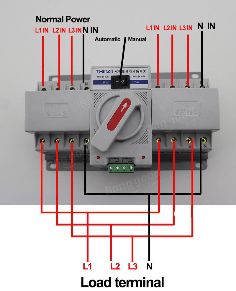
Automatic Transfer Switch Wiring

Ats Panel Wiring Automatic Transfer Switch Wiring Diagram Circuit An automatic transfer switch (ats) is an essential component in a backup power system. it allows for a smooth and seamless transition between the main power source and an alternate power source, such as a generator, in the event of a power outage. to properly control an automatic transfer switch, a wiring diagram is necessary. An auto transfer switch (ats) is an essential component of a backup power system. it is designed to automatically switch the power source from the main power grid to a backup generator in the event of a power outage. the wiring diagram of an ats illustrates how the various components are connected to ensure a smooth and reliable transfer.

Asco Automatic Transfer Switch Wiring Diagram Wiring Diagram Pictures Wiring 120v & 240, 1 phase manual transfer switch – nec. the following wiring diagram in fig 3 shows the reliance manual transfer switch connected to the main 120 240 v panel and a portable generator. step by step guide is posted before in the post under the title wiring a portable generator using manual transfer switch for 120 & 240v. Owner's manual automatic transfer switch. Here are the steps (8 in total) [silver cymbal]: step 1: attach a nail or screw to the transfer switch casing. step 2: mount the transfer switch casing. step 3: screw the casing to the wall securely. step 4: insert the transfer switch. step 5: secure the transfer switch to its casing. The generator is connected to the building’s electrical system via an automatic transfer switch (ats), which automatically switches between utility power dur.

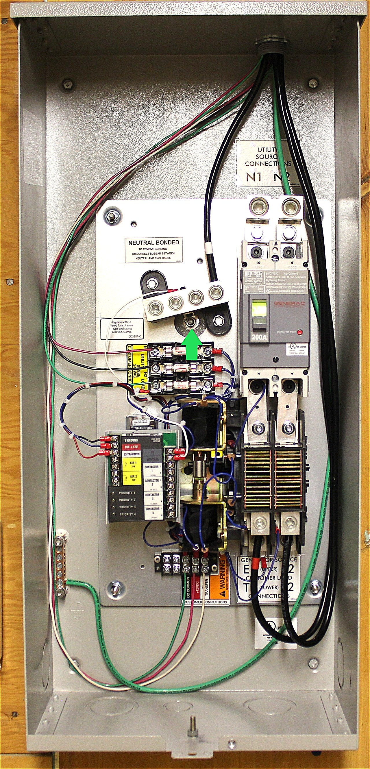
Generac Automatic Transfer Switch Wiring Here are the steps (8 in total) [silver cymbal]: step 1: attach a nail or screw to the transfer switch casing. step 2: mount the transfer switch casing. step 3: screw the casing to the wall securely. step 4: insert the transfer switch. step 5: secure the transfer switch to its casing. The generator is connected to the building’s electrical system via an automatic transfer switch (ats), which automatically switches between utility power dur. With an accurate ac voltmeter and frequency meter, check the no load, voltage and frequency. measure across ats terminal lugs e1 to e2, e2 to e3 and e1 to e3. neutral and e3 to neutral. it will also be necessary to verify that the phase rotation of the util ity matches the phase rotation of the generator. #automatictransferswitch #generac #standbygenerator #classicelectricnj how to wire a 200a service rated automatic transfer switch.electrical wiring is not a.

Generac Automatic Transfer Switch Wiring Diagram With an accurate ac voltmeter and frequency meter, check the no load, voltage and frequency. measure across ats terminal lugs e1 to e2, e2 to e3 and e1 to e3. neutral and e3 to neutral. it will also be necessary to verify that the phase rotation of the util ity matches the phase rotation of the generator. #automatictransferswitch #generac #standbygenerator #classicelectricnj how to wire a 200a service rated automatic transfer switch.electrical wiring is not a.

Comments are closed.