Basic Led Circuit Diagram

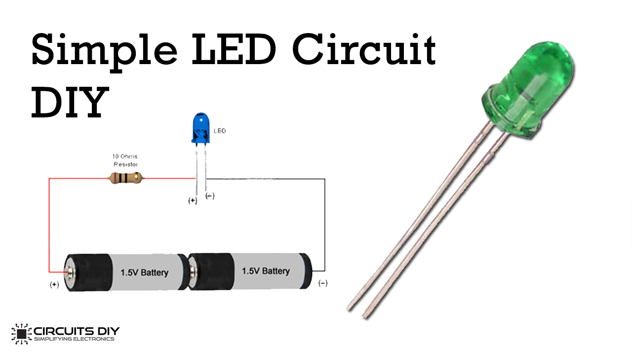
Simple Led Circuit Diagram Step 1: 3 volt basic led circuit with 10 ohms resistor. the above diagram shows a 3v led circuit, in this circuit there are two aa cells are used. when you are operating an led with 3v you have to use minimum 10 ohms resistor . for more details visit simple basic led circuit. The basic components in an led circuit diagram include the led itself, a power source (such as a battery or power supply), resistors, and wires. the led must be connected in the correct orientation, with the longer leg (anode) connected to the positive side of the power source and the shorter leg (cathode) connected to the negative side.

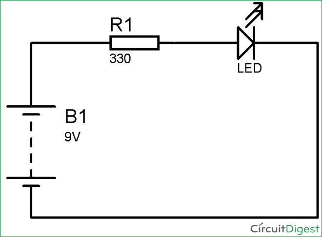
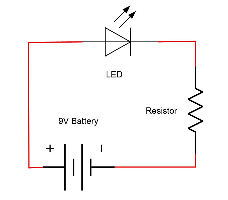
Simple Basic Led Circuit Beginner Electronics Project This video demonstration shows how to design and build a simple circuit to illuminate an led. the circuit is built on a breadboard, and uses a 9 v battery, r. As per the datasheet of the 5mm white led, the forward voltage of the led is 3.6v and the forward current of the led is 30ma. therefore, vs = 12v, vled = 3.6v and iled = 30ma. substituting these values in the above equation, we can calculate the value of series resistance as. rseries = (12 – 3.6) 0.03 = 280Ω. Again, my led is 1.7v, it takes 20ma (which is .02 a) of current and my supply is 4.5v. so the math is r = (4.5v 1.7v) .02 a r = 140 ohms once i knew that i needed a resistor of 140 ohms to get the correct amount of voltage to the led i looked into my assortment package of resistors to see if i could find the right one. Here is a diagram of the basic circuit. just as before, the led positive side is connected to the battery's positive side, and likewise negative to negative. the current will flow from the battery through the resistor and led and then back to the battery. the resistor and led are connected in series, which means one after the other.

тшс юааledюаб With Resistor юааcircuitюаб Again, my led is 1.7v, it takes 20ma (which is .02 a) of current and my supply is 4.5v. so the math is r = (4.5v 1.7v) .02 a r = 140 ohms once i knew that i needed a resistor of 140 ohms to get the correct amount of voltage to the led i looked into my assortment package of resistors to see if i could find the right one. Here is a diagram of the basic circuit. just as before, the led positive side is connected to the battery's positive side, and likewise negative to negative. the current will flow from the battery through the resistor and led and then back to the battery. the resistor and led are connected in series, which means one after the other. Leds (that's "ell ee dees") are a particular type of diode that convert electrical energy into light. in fact, led stands for "light emitting diode." (it does what it says on the tin!) and this is reflected in the similarity between the diode and led schematic symbols: in short, leds are like tiny lightbulbs. How to design a simple led circuit. which resistor to use, how to calculate the resistor.👉 👉👉 free design software ️ altium asp the engin.

Comments are closed.