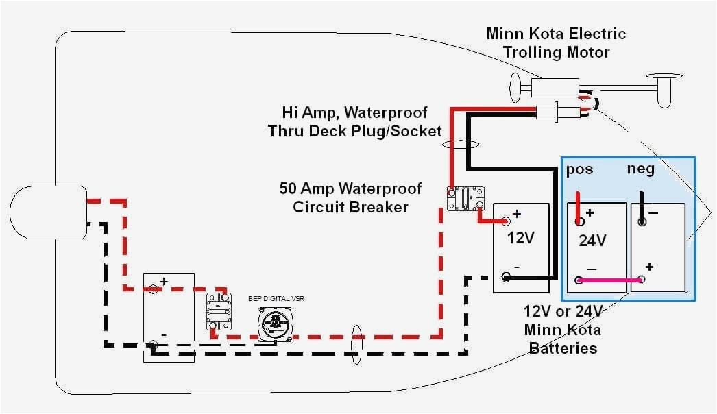
Boat For Trolling Motor Wiring Diagram Diagrams Schematics With 24 And

How To Hook Up 24v Trolling Motor Trolling motor wiring diagrams. while smaller, lighter boats may only require trolling motors wired to a single, 12v deep cycle marine battery, larger boats may need trolling motors with higher thrust and 24v and 36v systems with two or three 12v batteries, accordingly. for 24v and 36v trolling motors, batteries must be wired in "series" in. The following schematic outlines the necessary accessories cables needed to connect a trolling motor to a 24 volt system. compatible accessories. trolling motor; trolling motor plug *optional mkr 28 (1865120) 12 volt battery (2 batteries required) circuit breaker mkr 27 (1865115) red line = 12v dv power.

Trolling Motor Wiring Diagram 24 Volt These devices are available in three models: 12v, 24v, or 36v. the 24v motor is ideal for anglers who are looking for a better fishing experience at a more affordable rate than the 36v motor. the 24v trolling motor wiring schematic often shows two 12v batteries connected in a series. connecting two 12v batteries in series provides the 24v power. Step 1: gather the necessary equipment. before beginning the wiring process, ensure you have all the necessary equipment. this includes a motorguide 24 volt trolling motor, a marine battery bank with two 12 volt batteries, battery cables, a battery switch, and a circuit breaker. Trolling motor wiring. we get many requests for schematics on trolling motor wiring. there are a few different configurations one can use according to your trolling motor application and existing wiring that the manufacturer installed in your boat. the images below should help you resolve just how trolling motor wiring should be connected. Trolling motor manuals. for step by step instructions on how to mount or install your trolling motor, refer to the installation section of your owner's manual. download trolling motor installation and wiring guides with everything you need to know about how to install your minn kota motor or shallow water anchor.

3 Wire 24 Volt Trolling Motor Wiring Diagram Trolling motor wiring. we get many requests for schematics on trolling motor wiring. there are a few different configurations one can use according to your trolling motor application and existing wiring that the manufacturer installed in your boat. the images below should help you resolve just how trolling motor wiring should be connected. Trolling motor manuals. for step by step instructions on how to mount or install your trolling motor, refer to the installation section of your owner's manual. download trolling motor installation and wiring guides with everything you need to know about how to install your minn kota motor or shallow water anchor. The 4 wire 24 volt trolling motor wiring diagram includes four wires that are essential for the motor to function properly: two positive wires, one negative wire, and one jumper wire. the positive wires are usually colored red, and the negative wire is usually colored black. the jumper wire is used to connect the two positive wires together. Make sure that the trolling motor is disconnected. wire in series only as directed in wiring diagram, to provide 48 volts. connect a connector cable to the positive ( ) terminal of battery 1 and to the negative ( ) terminal of battery 2. the jumper wire used should be one size larger than the trolling motor lead wire.

Comments are closed.