Breadboard Circuit Tutorial Simple Led Youtube

Breadboard Circuit Tutorial Simple Led Youtube Learn how to build circuits from beginner to advanced in both on a breadboard and in tinkercad! this is a fun way to build new skills on your maker journey. This video demonstration shows how to design and build a simple circuit to illuminate an led. the circuit is built on a breadboard, and uses a 9 v battery, r.

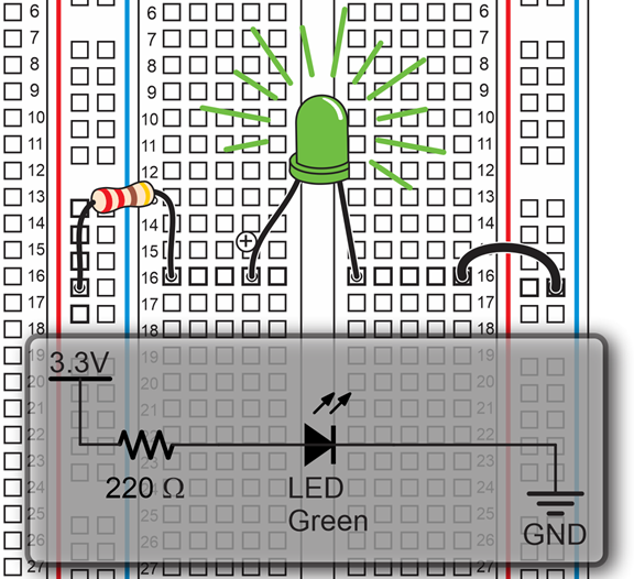
Circuit Diagram Vs Circuit Board #led #diyelectronics #circuit 🗳️ how to build a simple led circuit using an arduino in this tutorial, bryan deluca from maker build it walks you through the. Step 1: insert the led into the breadboard. start by bending the longer lead of the led as shown in the previous photo. plug the longer lead (anode) of the led into the top rail of the breadboard and the other lead into a hole in the main part of the breadboard as shown below. see the beginner's article on leds that explains how to identify the. Here’s a simple circuit diagram of a resistor and led connected to a 9v battery: to connect this circuit to a breadboard, first connect the resistor, making sure the pins are on different rows. then connect the led, making sure its negative leg is connected to the same row as the upper leg of the resistor. this is such a simple circuit, that. This photo shows the circuit built in this tutorial with the connecting strips of the breadboard that are used by the circuit in blue. current flow in the led circuit. the red lead from the battery is joined to the led via the top horizontal strip of the breadboard. the led connects to the resistor using a top vertical strip.

Register Cannot Driven By Primitives Or Continuous Assignment Miller Here’s a simple circuit diagram of a resistor and led connected to a 9v battery: to connect this circuit to a breadboard, first connect the resistor, making sure the pins are on different rows. then connect the led, making sure its negative leg is connected to the same row as the upper leg of the resistor. this is such a simple circuit, that. This photo shows the circuit built in this tutorial with the connecting strips of the breadboard that are used by the circuit in blue. current flow in the led circuit. the red lead from the battery is joined to the led via the top horizontal strip of the breadboard. the led connects to the resistor using a top vertical strip. Step 5. wire up the positive leads using red jumper wires. then connect from the positive rail of the breadboard to the same horizontal row as the top leg of the switch. now connect from the row that houses the bottom leg of the switch to the row that houses the anode of the led. Slide the stripped end of your jumper wire through the hole, and screw the post back down until the wire is firmly connected. typically, you only need to connect a power and ground wire from the posts to the breadboard. if you need an alternate power source, you can use the third post.

Comments are closed.