Cantilever Beam Deflection Formula Design Talk

Cantilever Beam Deflection Formula Pdf Design Talk Example cantilever beam with single load at the end, metric units. the maximum moment at the fixed end of a ub 305 x 127 x 42 beam steel flange cantilever beam 5000 mm long, with moment of inertia 8196 cm 4 (81960000 mm 4), modulus of elasticity 200 gpa (200000 n mm 2) and with a single load 3000 n at the end can be calculated as. m max. A cantilever beam is a structural element that extends horizontally and is supported on only one end. the unsupported end is known as the cantilever, and it extends beyond the support point. cantilever beams are often used in construction to support balconies, roofs, and other overhangs. they can also be used in bridges and other structures to.

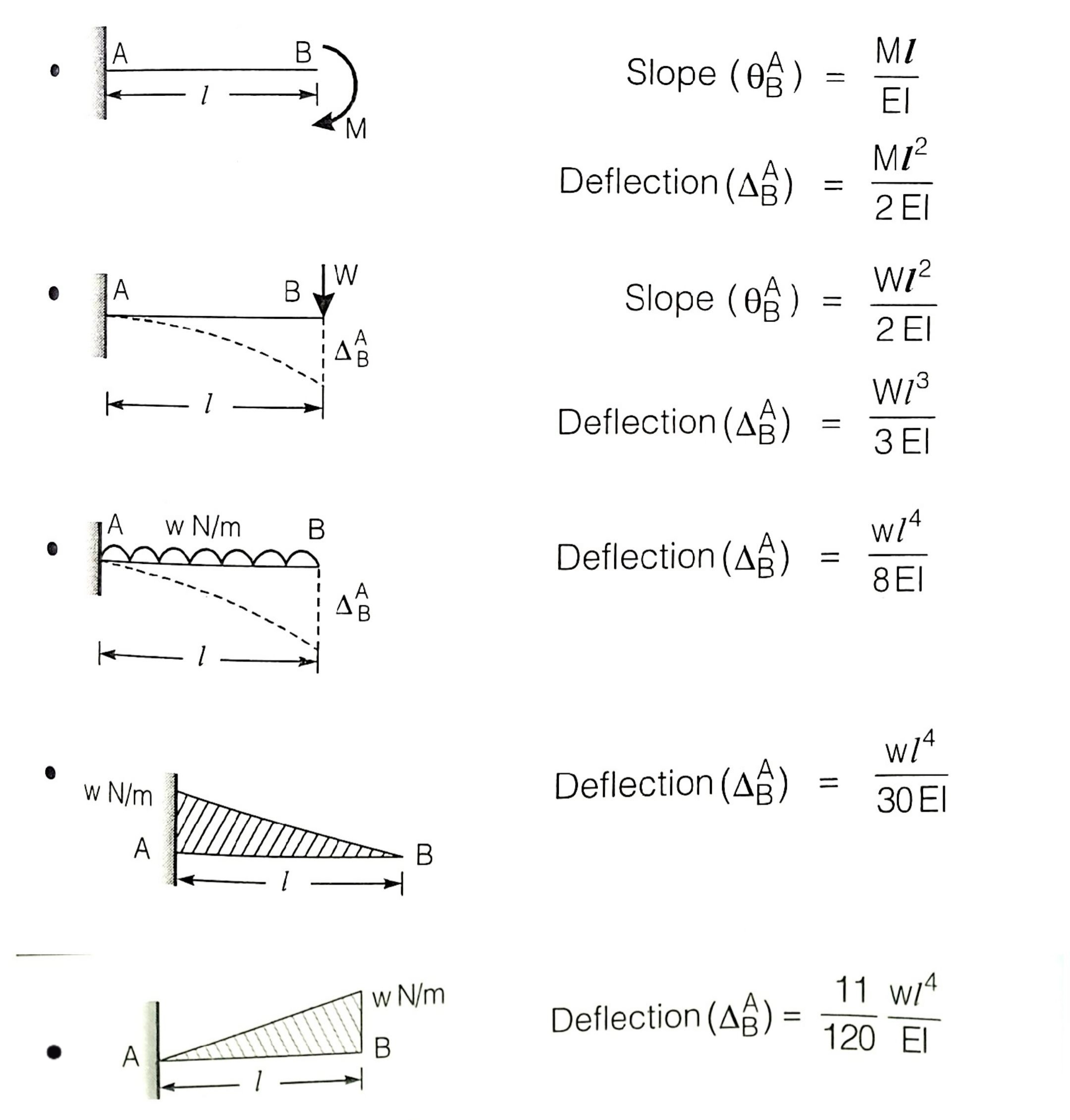
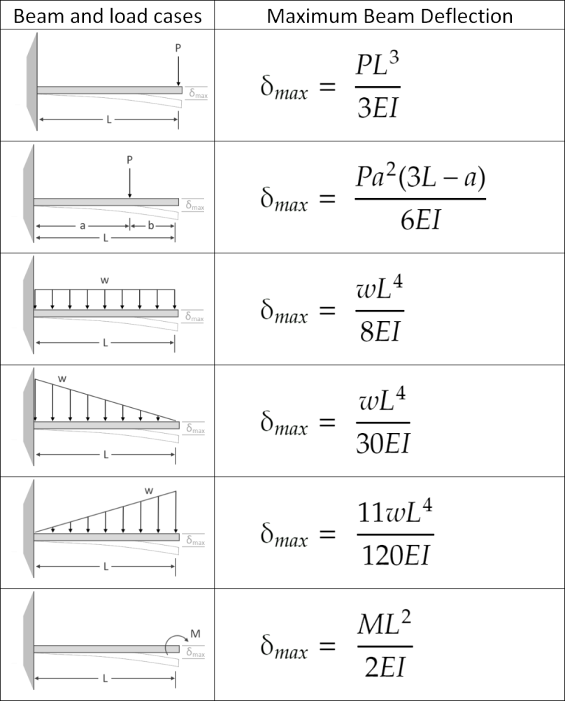
Cantilever Beam Deflection Limit Design Talk A cantilever beam shown in figure 7.10a is subjected to a concentrated moment at its free end. using the moment area method, determine the slope at the free end of the beam and the deflection at the free end of the beam. ei = constant. fig. 7.10. cantilever beam. solution (m ei) diagram. The general formulas for beam deflection are pl³ (3ei) for cantilever beams, and 5wl⁴ (384ei) for simply supported beams, where p is point load, l is beam length, e represents the modulus of elasticity, and i refers to the moment of inertia. however, many other deflection formulas allow users to measure different types of beams and deflection. 2. cantilever beam – concentrated load p at any point 2 pa 2 e i lei 2 3for0 px yax xa 6 ei 2 3for pa yxaaxl 6 ei 2 3 pa 6 la ei 3. cantilever beam – uniformly distributed load (n m) 3 6 l e i 2 22 64 x yxllx ei 4 max 8 l e 4. cantilever beam – uniformly varying load: maximum intensity o 3 o 24 l e i 2 32 23 o 10 10 5 120 x yllxlxx 4 o. Figure 3 – design aid tables (beam design equations and diagrams) – pci design handbook 4. flexural design 4.1. required and provided reinforcement for this beam, the moment at the fixed end governs the design as shown in the previous figure. mu t use #9 bars with 1.5 in. concrete clear cover per aci 318 14 (table 20.6.1.3.1). the distance.

Cantilever Beam Deflection Calculation Example Design Talk 2. cantilever beam – concentrated load p at any point 2 pa 2 e i lei 2 3for0 px yax xa 6 ei 2 3for pa yxaaxl 6 ei 2 3 pa 6 la ei 3. cantilever beam – uniformly distributed load (n m) 3 6 l e i 2 22 64 x yxllx ei 4 max 8 l e 4. cantilever beam – uniformly varying load: maximum intensity o 3 o 24 l e i 2 32 23 o 10 10 5 120 x yllxlxx 4 o. Figure 3 – design aid tables (beam design equations and diagrams) – pci design handbook 4. flexural design 4.1. required and provided reinforcement for this beam, the moment at the fixed end governs the design as shown in the previous figure. mu t use #9 bars with 1.5 in. concrete clear cover per aci 318 14 (table 20.6.1.3.1). the distance. Examining the deflected shape geometry results, the masterframe gives a deflection of 2.9mm for the vertical (y axis) deflection of the cantilever. the tabular results gives the deflection of node n4 as 2.88mm. the difference is due to rounding in the graphical results area. checking this using the standard deflection formula (8) we then have. Notations relative to “shear and moment diagrams”. e = modulus of elasticity, psi i = moment of inertia, in.4. l = span length of the bending member, ft. = span length of the bending member, in. = maximum bending moment, in. lbs. = total concentrated load, lbs. = reaction load at bearing point, lbs.

Large Deflection Diagram Of Cantilever Beam Under Dis Vrogue Co Examining the deflected shape geometry results, the masterframe gives a deflection of 2.9mm for the vertical (y axis) deflection of the cantilever. the tabular results gives the deflection of node n4 as 2.88mm. the difference is due to rounding in the graphical results area. checking this using the standard deflection formula (8) we then have. Notations relative to “shear and moment diagrams”. e = modulus of elasticity, psi i = moment of inertia, in.4. l = span length of the bending member, ft. = span length of the bending member, in. = maximum bending moment, in. lbs. = total concentrated load, lbs. = reaction load at bearing point, lbs.

Cantilever Beam Deflection Formula Design Talk

Comments are closed.