Car Iso Wiring Diagram

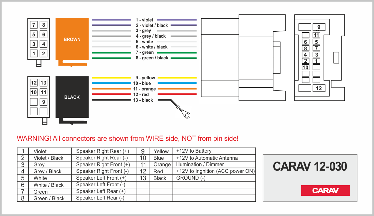
Iso Wiring Diagram The connector wiring may vary depending on the car manufacturer! take special care when installing into ’98 or later vw audi skoda seat models as there may be a 12 v connection on pin a5, which could damage the car stereo or into ford from ’97 or later, with an iso connector, on which damage to the car’s microcomputers is possible if misconnected. The most common iso stereo wiring colours include red, yellow, black, blue, green, purple, and white. while these colours may vary slightly depending on the manufacturer, they generally follow the same colour coding scheme. for example, red usually represents the power wire, yellow is for the constant power wire, black is the ground wire, blue.

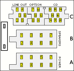
Car Radio Iso Wiring Diagram Step 1: remove the old connector. the first step in the installation process is to remove the old iso connector from the car radio. to do this, use a screwdriver to remove the screws that hold the connector in place. once the screws are removed, carefully pull the connector out of the car radio. Here are the common stereo wire colors and their meanings: constant power (yellow): provides continuous power to the stereo, even when the car is off, to maintain memory settings. switched power (red): supplies power to the stereo only when the car’s ignition is on (accessory or radio position). ground (black): connects the stereo to the car. Connections for block c mini iso – left hand side, uses yellow plug. 1) line out left rear . 4) line out left front. 3) line out ground earth. 6) switched positive for amplifier. 2) line out right rear . 5) line out right front. connections for block c – centre, uses green plug. 7) tel ve. It is a universal wiring configuration that allows car enthusiasts to easily connect their stereo system without the need for complicated wiring diagrams or adapters. the iso wiring system consists of a set of standard wire colors and connectors that are used in most car stereo installations.

Car Stereo Wiring Harness Adapter Connections for block c mini iso – left hand side, uses yellow plug. 1) line out left rear . 4) line out left front. 3) line out ground earth. 6) switched positive for amplifier. 2) line out right rear . 5) line out right front. connections for block c – centre, uses green plug. 7) tel ve. It is a universal wiring configuration that allows car enthusiasts to easily connect their stereo system without the need for complicated wiring diagrams or adapters. the iso wiring system consists of a set of standard wire colors and connectors that are used in most car stereo installations. Here is a color code car stereo wiring diagram you can use: an explanation of the car stereo wires color code when you don’t have a wiring diagram is as follows: black ground wire that you connect to an unpainted part of the chassis. yellow connect to a constant 12 voltage battery source. red connects to the accessory and turns on with the. 4. understanding color codes: auto stereo wiring diagrams often include color codes for the wires. these codes indicate the purpose of the wire, such as power, ground, or speaker connections. understanding these color codes will help you make the correct connections and avoid any potential issues. red: power.

Diagram Civic Iso Wires Diagrame Mydiagram Online Here is a color code car stereo wiring diagram you can use: an explanation of the car stereo wires color code when you don’t have a wiring diagram is as follows: black ground wire that you connect to an unpainted part of the chassis. yellow connect to a constant 12 voltage battery source. red connects to the accessory and turns on with the. 4. understanding color codes: auto stereo wiring diagrams often include color codes for the wires. these codes indicate the purpose of the wire, such as power, ground, or speaker connections. understanding these color codes will help you make the correct connections and avoid any potential issues. red: power.

Toyota Fujitsu Ten 86120 Wiring Diagram Wiring Diagram

Comments are closed.