Car Radio Connection Diagram

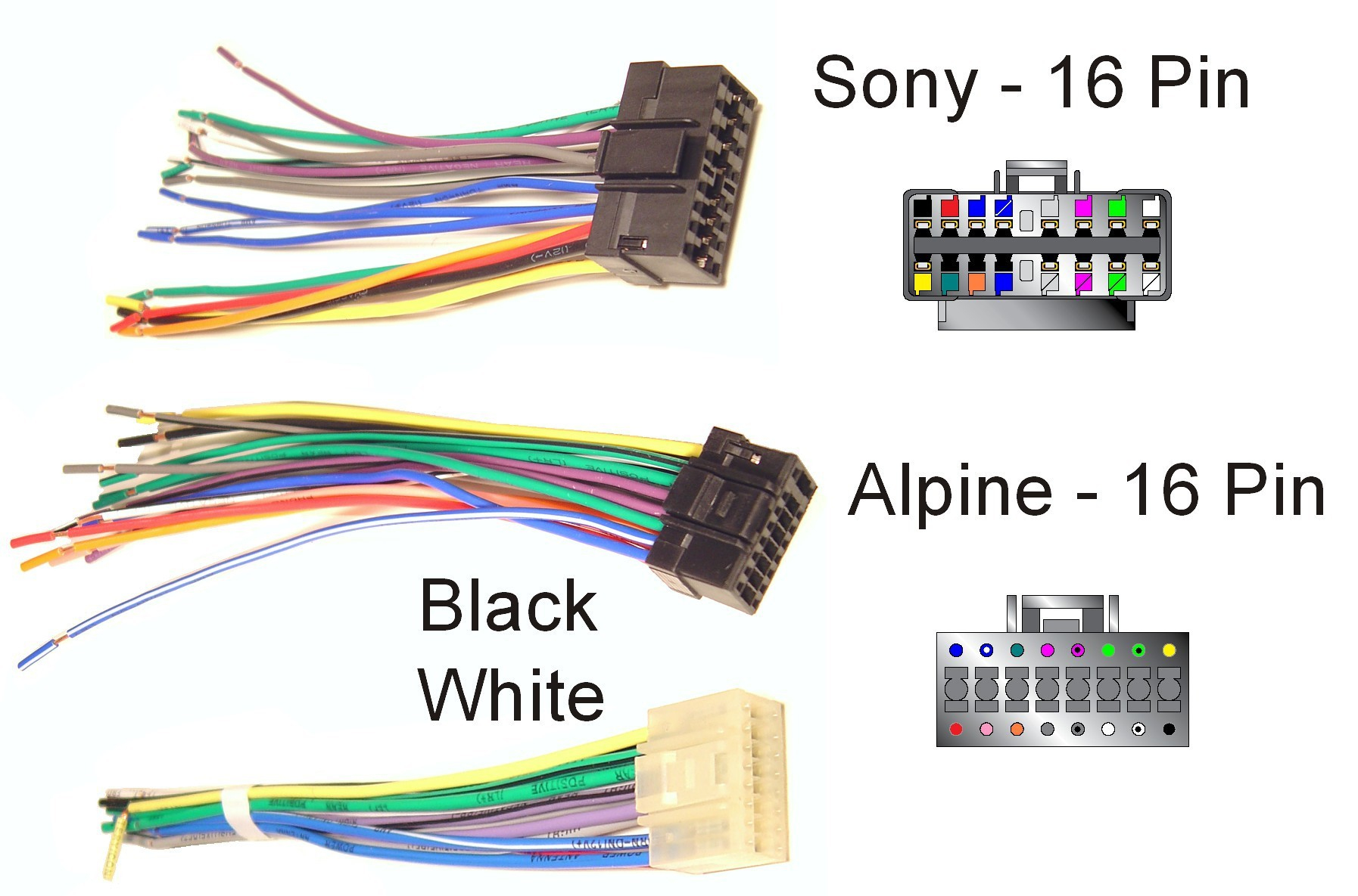
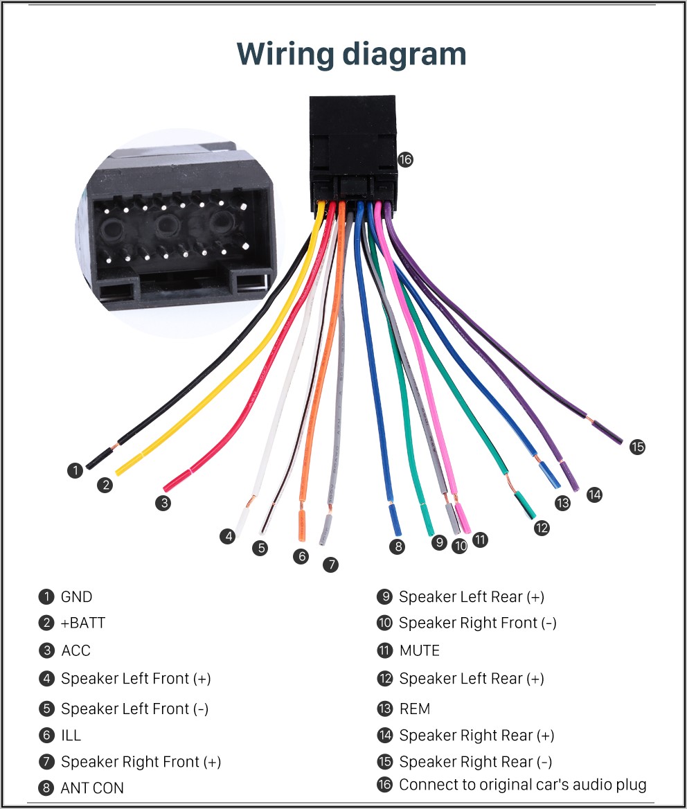
Sony Stereo Wire Diagram Wiring Diagram Sony Radio Wiring Diagram Here are the common stereo wire colors and their meanings: constant power (yellow): provides continuous power to the stereo, even when the car is off, to maintain memory settings. switched power (red): supplies power to the stereo only when the car’s ignition is on (accessory or radio position). ground (black): connects the stereo to the car. Our complete car radio wiring diagrams shows you all the stereo wire harness colors, car speaker wiring colors and car speaker sizes. each car radio wiring diagram lists information from hands on experience or is provided by our community that is verified. that’s why you can be sure you’re getting the most accurate car radio.

Car Stereo Radio Wiring Diagram Find and connect all loose wires (using an output converter, if needed). secure all your wires into place, using methods like soldering or twisting. test the stereo and install it into your car. secure the stereo with bolts or spring clips and reinstall the old trim. part 1. These harnesses usually include a color coded wiring diagram for connecting the harness to your new stereo. your new stereo will also include a radio wiring diagram in the owner's manual. refer to the two diagrams to confirm the car stereo wire colors that need to be connected to the adapter harness. The first step to installing a new car stereo is connecting the stereo's wiring harness to the adapter that will plug into your car. making long lasting, secure wire connections is of the utmost importance. by using one or more of the methods illustrated below, you can be sure that your connections will last for years to come—and that your. The car radio wiring harness diagram typically consists of various color coded wires, each representing a different function. for example, the red wire in the diagram may indicate the power supply, while the black wire represents the ground connection. other wires may be dedicated to speaker connections, antenna, and auxiliary inputs.

Comments are closed.