Cd 4026 Circuit Diagram

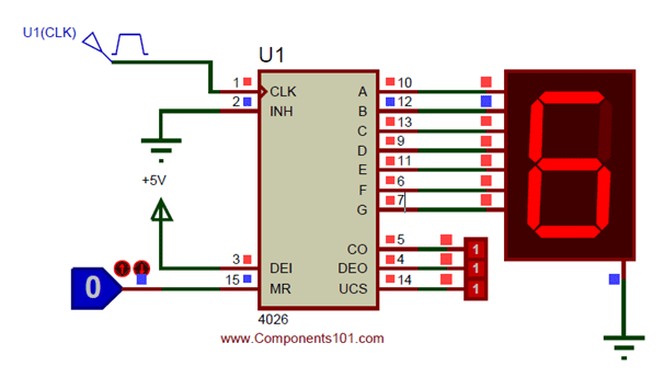
4026b Datasheet Pdf Additionally, the advantage of using this ic is that it has a built in decoder circuit along with the counter and it can be connected to all types of 7 segment displays.the ten decoding outputs go high sequentially on positive edge of input clock cycle. cd4026 pinout diagram. this picture shows a pinout diagram of 5 stage johnson decade counter. The ic cd4026 is an ic which can perform the function of both a counter as well a 7 segment drive r. one single ic can be used to count form zero (0) to nine (9) directly on a common cathode type 7 segment display. the count can be increased by simply giving a high clock pulse; also more than one digit (0 9) can be created by cascading more.

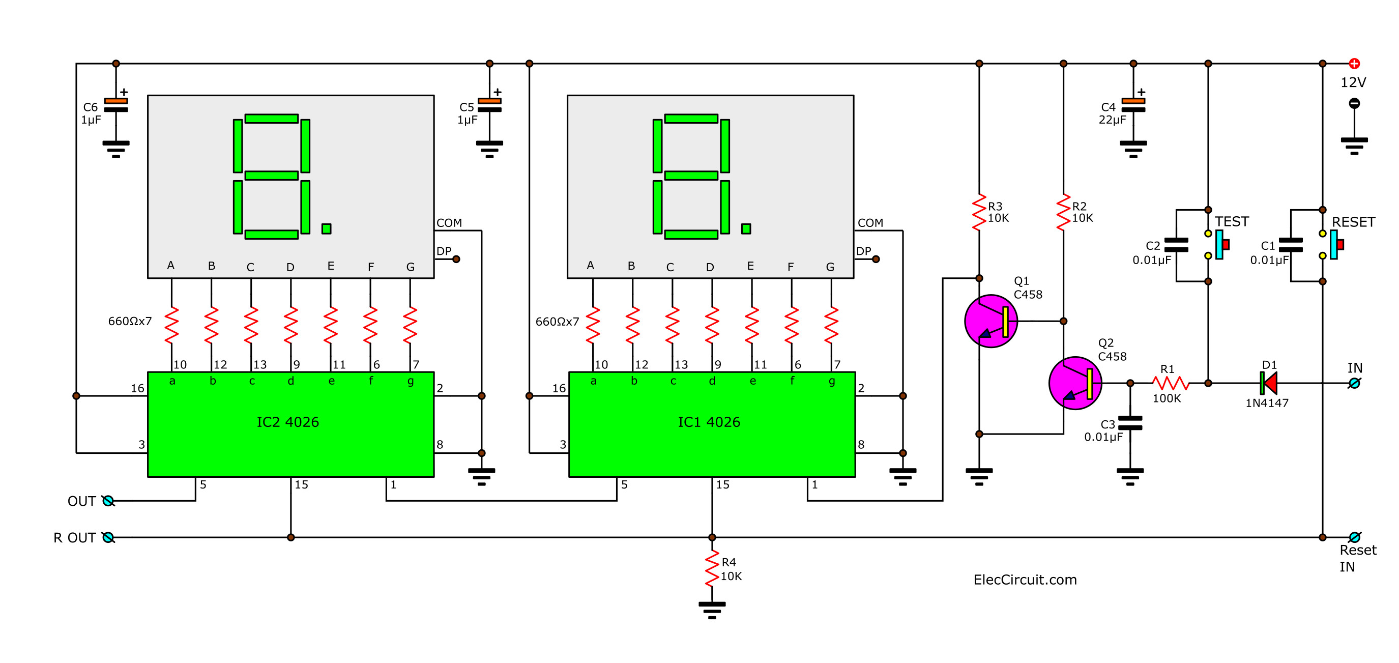
Cd4026 Ic Pinout Example Circuits Applications Datasheet And Features Working explanation. a simple circuit uses a 555 timer ic, a decade counter ic 4026 and a seven segment (common cathode type) led. the 555 ic is configured in a monostable multivibrator mode that produces a pulse each time the count key is pressed. the clock pulse is an input to the ic 4026 that counts each pulse and derives the seven segments led. Ic cd4026. 4026 ic is a 4000 series ic. it is a cmos seven segment counter ic and can be operated at very low power. it is a decade counter, counts in decimal digits (0 9). it is used to display numbers on seven segment displays and it increment the number by one, when a clock pulse is applied to its pin 1. As the circuit below. the ic1, ic2 cd4026 (cmos counters decade divider integrated circuit). i like this ic. because they can drive led 7 segment directly. recommended: 0 99 counter using ttl 74ls48, 74ls90. which they connected together. ic1 is a unit counter ic. ic2 is a ten digit counter. and both ics will work at rising edged clock only. In this video, i've explained the basic things on 4026 and how to operate this with a practical circuit in the breadboard. this is the first part of 4026 ic .

2 Digit Simple Digital Counter Circuit Using Cd4026 As the circuit below. the ic1, ic2 cd4026 (cmos counters decade divider integrated circuit). i like this ic. because they can drive led 7 segment directly. recommended: 0 99 counter using ttl 74ls48, 74ls90. which they connected together. ic1 is a unit counter ic. ic2 is a ten digit counter. and both ics will work at rising edged clock only. In this video, i've explained the basic things on 4026 and how to operate this with a practical circuit in the breadboard. this is the first part of 4026 ic . The schematic diagram shows you how to connect the ic's and displays together. note that for this test circuit we are using push buttons for clocking, resetting and disabling the display. any clean clock pulse source can be used to increment the display and if you want you can just tie the display enable pins high permanently. First, check that your battery has any juice left 🙂 make sure the power rails on both sides are connected properly (step 1). also make sure that the “display enable in” pin of the cd4026 is connected to 9v (step 8). also check if pin 8 of the 7 segment display is connected to ground via the 470Ω resistor (step 6).

4026 Pinout The schematic diagram shows you how to connect the ic's and displays together. note that for this test circuit we are using push buttons for clocking, resetting and disabling the display. any clean clock pulse source can be used to increment the display and if you want you can just tie the display enable pins high permanently. First, check that your battery has any juice left 🙂 make sure the power rails on both sides are connected properly (step 1). also make sure that the “display enable in” pin of the cd4026 is connected to 9v (step 8). also check if pin 8 of the 7 segment display is connected to ground via the 470Ω resistor (step 6).

Counter Circuit Diagram Wiring Diagram And Schematics

Comments are closed.