Change Over Switch Wiring Three Phase Na Single Phase

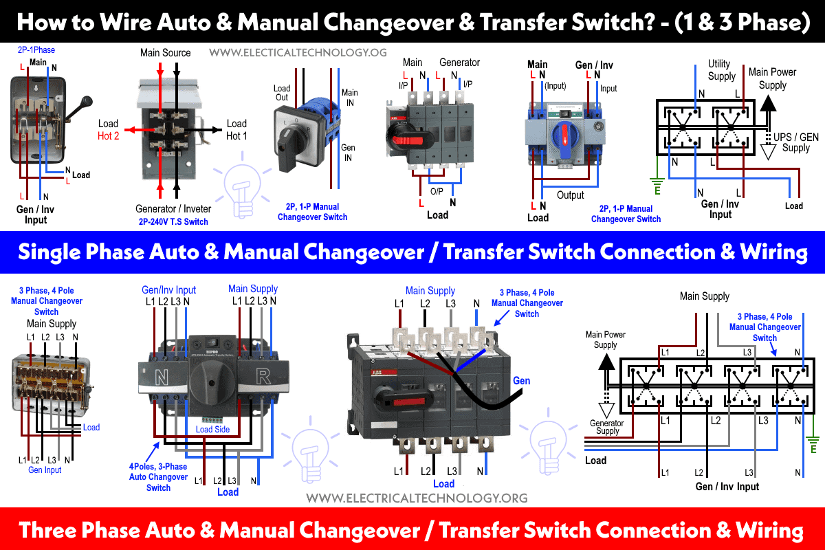
3 Phase Changeover Switch Wiring Diagram Wiring 120v & 240, 1 phase manual transfer switch – nec. the following wiring diagram in fig 3 shows the reliance manual transfer switch connected to the main 120 240 v panel and a portable generator. step by step guide is posted before in the post under the title wiring a portable generator using manual transfer switch for 120 & 240v. How to wire a single phase change over switch to a three phase db board.one phase connected to changeover for generator backup power.

How To Wire A Single Phase Change Over Switch To A 3 Ph About press copyright contact us creators advertise developers terms privacy policy & safety how works test new features nfl sunday ticket press copyright. Automatic transfer switch ats forms the interface between the gen set utility power and the consuming electrical equipment it performs three functions it mon. A typical three phase manual changeover switch wiring diagram is composed of four main parts: the power source, the load, the switch, and the control panel. the power source is typically the main power supply, which could be a generator, a local utility, or a combination of both. the load is connected between the power source and the switch. When connecting the three phase motor to the single phase power supply, it is necessary to correctly identify and connect the motor’s leads. the motor will have three leads for each phase, labeled l1, l2, and l3. these leads should be connected to the appropriate wires of the single phase power supply.

Automatic Changeover Switch Schematic Diagram A typical three phase manual changeover switch wiring diagram is composed of four main parts: the power source, the load, the switch, and the control panel. the power source is typically the main power supply, which could be a generator, a local utility, or a combination of both. the load is connected between the power source and the switch. When connecting the three phase motor to the single phase power supply, it is necessary to correctly identify and connect the motor’s leads. the motor will have three leads for each phase, labeled l1, l2, and l3. these leads should be connected to the appropriate wires of the single phase power supply. A single phase changeover switch is a device used to switch between two different sources of power. this is especially useful when you need to switch between two different voltage levels or sources. for example, you might use one to switch between a generator and the power grid, or between two different voltage levels within a single system. Step 1: tools and material. following materials were used: 1. 1 cm and 5mm thick mdf board. 2. 63 amp, 4 pole changeover switch (on load type) 3 (its l&t make, model number was not mentioned anywhere.) 3. 63 amp rated, 3 terminal connectors 2. 4. 0 230 v digital voltmeter 1. 5.

Comments are closed.