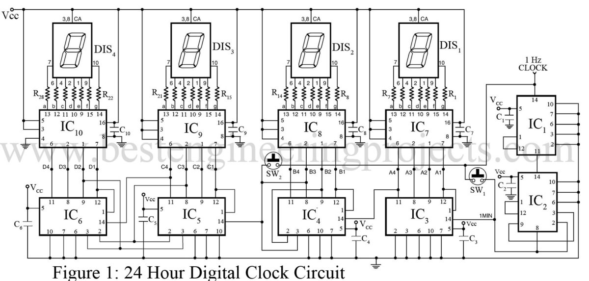
Circuit Diagram Of Digital Clock Pdf

Digital Clock Circuit Diagram Pdf Design, implementation and simulation of 24h digital. Build a clock circuit that will generate a low frequency periodic sig nal. on each clock pulse, the robot will advance one instruction forward in its memory. in the previous lab exercise, we introduced the principle of digital circuits, where we consider the circuits to only have two kinds of output voltages – high and low.

Circuit Diagram Of Digital Clock Pdf A digital clock is a repeating digital waveform used to step a digital circuit through a sequence of states. we will introduce the 555 timer chip and use it to generate a clock signal. digital circuits able to step through a sequence of states with the aid of flip flops and a clock are called sequential logic. A few nand gates and d flipflops have been used to ensure proper functioning of the clock. there is only one input for the entire system: the clock input into the 0 9 counter used for the unit’s digit of minute. the clock inputs for the other blocks are derived from the output of the previous blocks as shown in the block diagram for the system. All the circuit is power at 5v. note: the accuracy of this digital clock depends on how accurate you bring the ic 555 pulse to 1 hz. ic 4026 to 7 segment display connection: ic 4026 to 7 segment display connection. you need to connect the 220 ohm resistor to each segment as shown above. It makes life a lot easier afterwards. so this is the final circuit that i came up with. you can find the circuit diagram in the attached pdf. i will use a diy arduino on board as a microcontroller. if you aren't sure about what i am talking, follow the links below. circuit diagram bit.ly 2tvzsxb. make diy arduino uno bit.ly.

Digital Clock Circuit Diagram Using 7490 Pdf Wiring Diagram And All the circuit is power at 5v. note: the accuracy of this digital clock depends on how accurate you bring the ic 555 pulse to 1 hz. ic 4026 to 7 segment display connection: ic 4026 to 7 segment display connection. you need to connect the 220 ohm resistor to each segment as shown above. It makes life a lot easier afterwards. so this is the final circuit that i came up with. you can find the circuit diagram in the attached pdf. i will use a diy arduino on board as a microcontroller. if you aren't sure about what i am talking, follow the links below. circuit diagram bit.ly 2tvzsxb. make diy arduino uno bit.ly. You can build a digital clock with a large 7 segment display, a feather rp2040, and circuitpython no internet required! for time keeping, this build uses the ds3231 real time clock module for precise and accurate timing. easy time setting a rotary encoder is used to set the time, making daylight savings time changes easy and intuitive. A digital clock is a repeating digital waveform used to step a digital circuit through a sequence of states. we will introduce the 555 timer chip and use it to generate a clock signal. digital circuits able to step through a sequence of states with the aid of flip flops and a clock are called sequential logic.

Comments are closed.