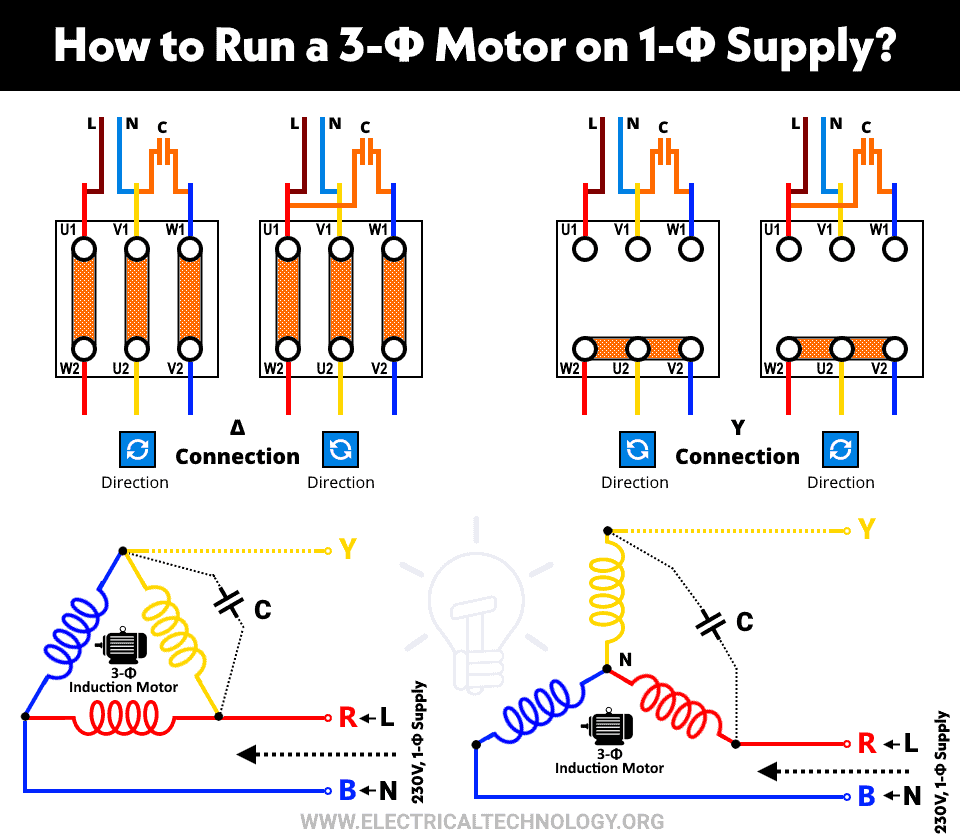
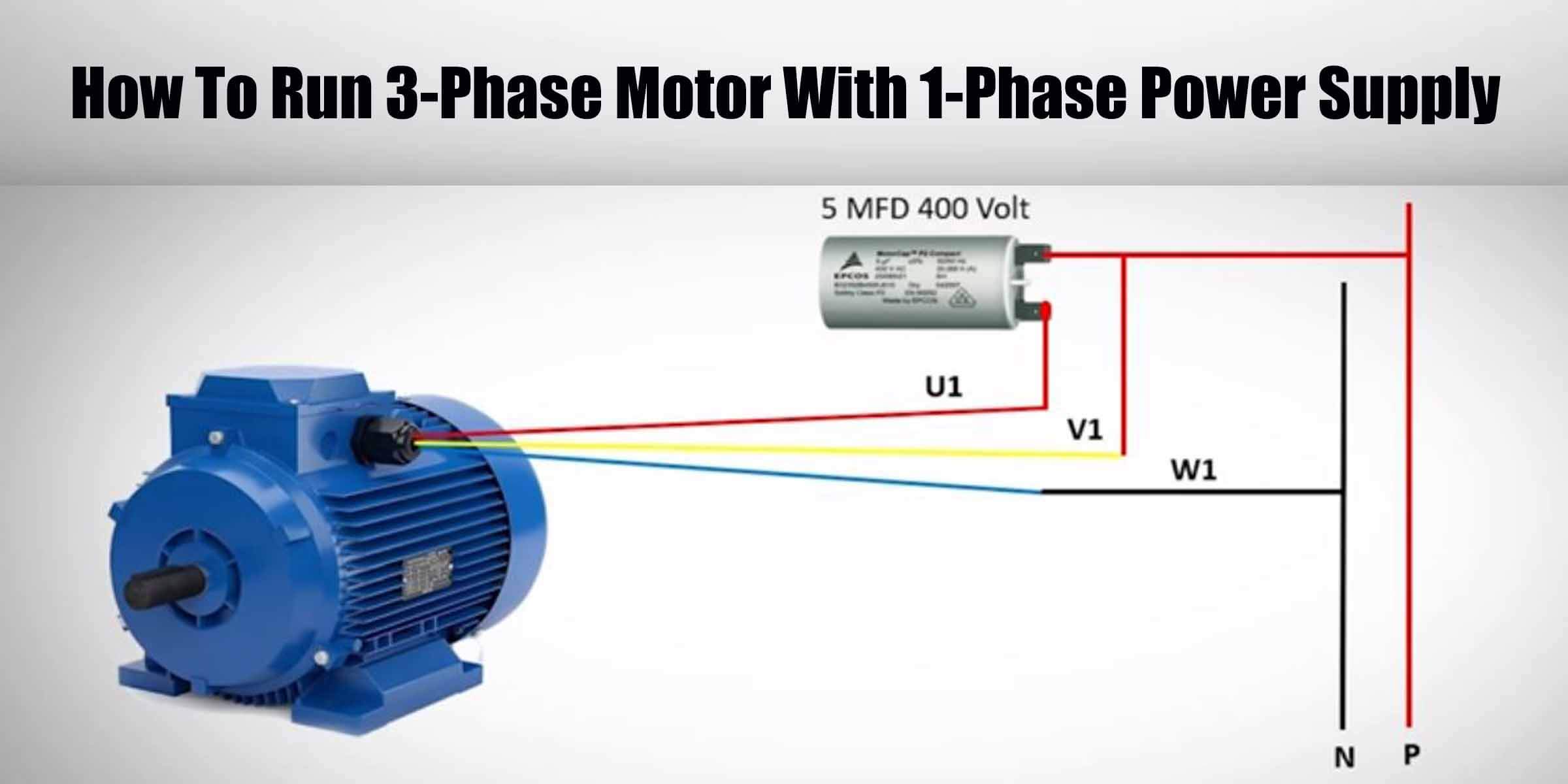
Connecting A 3 Phase Motor With 1 Phase Power With Diagram

What Happens If You Connect A 3 о Motor To 1 Phase Supply The three main components of a 3 phase wiring diagram for motors are: power supply: the diagram shows the three phase power supply, typically labeled as l1, l2, and l3. these represent the three separate phases of the power source. motor: the diagram illustrates the motor as a single unit with labeled terminals. The three phase motor connection diagram typically consists of three sets of wires, labeled as “t1”, “t2”, and “t3”. these wires correspond to the three phases of the electrical system and are used to supply power to the motor. in addition to these three wires, there may also be other wires labeled with letters such as “u”, “v.

How To Run 3 Phase Motor With 1 Phase Power Supply Engineering Three phase motor connection star delta without timer – power & control diagrams. three phase motor connection star delta (y Δ) reverse forward with – timer power & control diagram. starting & stopping of 3 phase motor from more than one place power & control diagrams. control 3 phase motor from more than two buttons – power & control. Because the voltage level of the three phase supply is 400 440 v and the voltage level of the single phase supply is 200 230 v for 50 hz of supply. we can use this circuit without using an autotransformer. in that case, the voltage level remains at single phase power (200 230 v). in this condition also, the motor will run. To wire a 3 phase motor, first, identify the wires and check the wiring diagram on the motor. 6 wires are from the motor, 1 for grounding if provided, and 3 (l1 3) from the power supply. choose one of the two configurations (star or delta) and connect the wires to the terminals accordingly. then, connect the ground wire to the grounding. The diagram of a three phase motor typically includes several key components. the three power connections, often labeled as l1, l2, and l3, represent the three phases of the motor. these connections are usually connected to a motor controller or starter that regulates the voltage and frequency supplied to the motor.

How To Connecting A 3 Phase Motor With 1 Phase Power With Diagram To wire a 3 phase motor, first, identify the wires and check the wiring diagram on the motor. 6 wires are from the motor, 1 for grounding if provided, and 3 (l1 3) from the power supply. choose one of the two configurations (star or delta) and connect the wires to the terminals accordingly. then, connect the ground wire to the grounding. The diagram of a three phase motor typically includes several key components. the three power connections, often labeled as l1, l2, and l3, represent the three phases of the motor. these connections are usually connected to a motor controller or starter that regulates the voltage and frequency supplied to the motor. Step 3: connect the motor’s terminals. using the wiring diagram as a guide, identify the motor’s terminals and connect them appropriately. this typically involves connecting the three phase wires to the motor’s three terminals, following the diagram’s instructions for proper placement. Wiring a three phase motor is an essential step in industrial and commercial electrical installations. three phase motors are commonly used in various applications, such as pumps, fans, compressors, and more. these motors provide a higher power output compared to their single phase counterparts, making them ideal for heavy duty operations.

Comments are closed.