Coolant Temperature Sensor Wiring Diagram
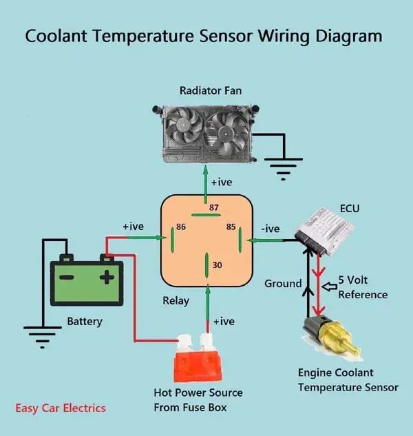
1 2 3 Wire Coolant Temperature Sensor Wiring Diagram 3 wire coolant temperature sensor wiring diagram. the two wires, a “5 volt reference”, and a “ground wire” go to the ecu, and the third wire “earth 1 wire for temp gauge” goes to the cluster mounted temperature gauge by providing an earth link to the temperature gauge. in three wire coolant temp sensors, the ecu does not control the. The engine coolant temperature sensor (ect) wiring diagram serves two main purposes: it provides a reliable source of signal information that allows you to monitor the temperature of your engine coolant fluid, and it ensures that the proper wattage is being used to power the sensor's electrical components. the wiring diagram consists of several.
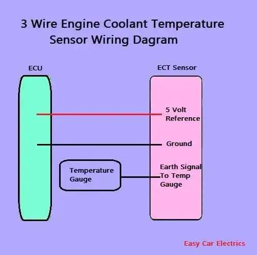
1 2 3 Wire Coolant Temperature Sensor Wiring Diagram The wiring diagram for the coolant temperature gauge typically includes three main components: the temperature sensor, the gauge, and the power source. the temperature sensor is connected to the engine block, while the gauge is connected to the dashboard. The coolant temperature sensor wiring diagram is composed of three central elements: the power supply, the coolant temperature sensor, and the output side. the power supply provides the energy needed to operate the coolant temperature sensor. from here, the electrical current travels through the coolant temperature sensor, which either. The coolant temp sensor wiring diagram illustrates the electrical connections for the sensor. it typically includes the wire colors, connector pinouts, and any related components in the circuit. the diagram acts as a guide for mechanics, technicians, and car enthusiasts who need to understand how the sensor is wired to ensure accurate readings. The testing steps of the ect goes as follows: disconnecting the ect sensor from the electrical connector. measure the temperature of the surface of the engine using either a cooking thermometer or an infrared thermometer. note the temperature reading of the surface of the engine. set the digital multimeter to the resistance settings.
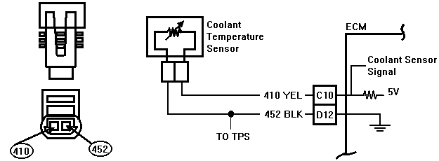
Code 15 Coolant Temperature Sensor Circuit The coolant temp sensor wiring diagram illustrates the electrical connections for the sensor. it typically includes the wire colors, connector pinouts, and any related components in the circuit. the diagram acts as a guide for mechanics, technicians, and car enthusiasts who need to understand how the sensor is wired to ensure accurate readings. The testing steps of the ect goes as follows: disconnecting the ect sensor from the electrical connector. measure the temperature of the surface of the engine using either a cooking thermometer or an infrared thermometer. note the temperature reading of the surface of the engine. set the digital multimeter to the resistance settings. The wiring diagram for the engine coolant temperature sensor typically includes three wires: a power supply wire, a ground wire, and a signal wire. the power supply wire provides voltage to the sensor, while the ground wire completes the circuit. the signal wire carries the temperature data from the sensor to the ecu. Firmly grasp the electrical connector and gently push it back onto the coolant sensor until you hear an audible click signaling the complete installation of the connector. 6. refill the cooling system. once the sensor installation is complete, close the radiator drain valve and refill the system with coolant.
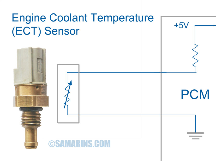
3 Wire Coolant Temperature Sensor Wiring Diagram Asmaaakasha The wiring diagram for the engine coolant temperature sensor typically includes three wires: a power supply wire, a ground wire, and a signal wire. the power supply wire provides voltage to the sensor, while the ground wire completes the circuit. the signal wire carries the temperature data from the sensor to the ecu. Firmly grasp the electrical connector and gently push it back onto the coolant sensor until you hear an audible click signaling the complete installation of the connector. 6. refill the cooling system. once the sensor installation is complete, close the radiator drain valve and refill the system with coolant.
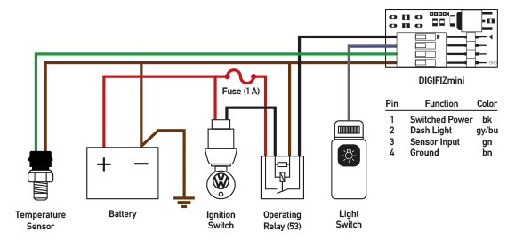
3 Wire Coolant Temperature Sensor Wiring Diagram Asmaaakasha

Comments are closed.