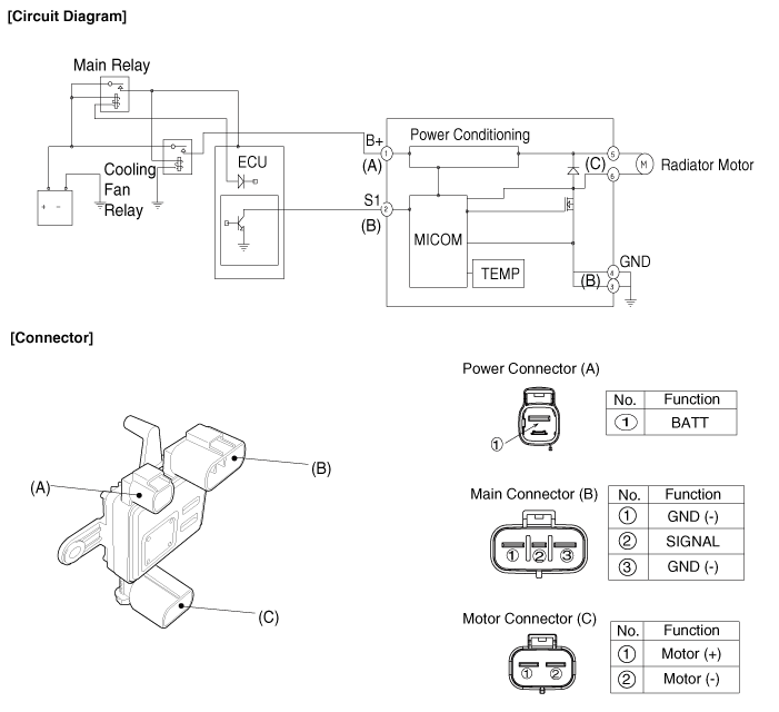
Cooling Fan Circuit Diagram 05 Quest

Cooling Fan Circuit Diagram 05 Quest Here you will find fuse box diagrams of nissan quest 2004, 2005, 2006, cooling fan (no.1) r7: cooling fan relay 1, cooling fan relay 3: i: 40: circuit breaker. On the fuse diagram, find the number of the fuse you want to check. the diagram tells you where to locate the fuse on the panel. pinch the fuse perpendicularly with the fuse puller and pull it out. to check a fuse, look at the silver colored band inside the fuse. if the band is broken or melted, replace the fuse with a new one.

Cooling Fan Circuit Diagram 05 Quest The fsm also describes testing the various harnesses and connections between the relays, fan motors, and the cpu. the cpu is supplying the 12v to the motor windings and the relay operation supplies the ground. the relays supply ground to various windings of the motors for the different speeds. the fsm also cautions not to overheat the engine. 15. body control module (bcm), automatic interior mirror to prevent dazzling. 4. 10. audio, av switch, display unit, display control unit, navigation control unit, dvd player, satellite radio tuner, body control module (bcm) 5. 15. front power socket 2, rear power socket (2nd row) 6. Cooling fan circuit diagram 05 quest. kia sorento: cooling fan circuit diagram cooling system engine buick rendezvous wiring switch correctly 2carpros fan relay electric diagram. cooling fans not working correctly: cooling fans on my, page 2repair guides cooling fan circuit diagram 05 questcooling fan speed control circuit. Start your wiring project by taking both of the positive wires from the fans and run them to the yellow wires on each relay (tab 87). then connect switched power (usually from your ignition switch), to the blue wires on both relays (tab 86). next, splice together both black wires from the relays (tab 85) and connect them to the thermostat switch.

Cooling Fan Circuit Diagram 05 Quest Cooling fan circuit diagram 05 quest. kia sorento: cooling fan circuit diagram cooling system engine buick rendezvous wiring switch correctly 2carpros fan relay electric diagram. cooling fans not working correctly: cooling fans on my, page 2repair guides cooling fan circuit diagram 05 questcooling fan speed control circuit. Start your wiring project by taking both of the positive wires from the fans and run them to the yellow wires on each relay (tab 87). then connect switched power (usually from your ignition switch), to the blue wires on both relays (tab 86). next, splice together both black wires from the relays (tab 85) and connect them to the thermostat switch. When the ignition is turned on the cooling fan relay is energized, closing a contact to short out the slow speed resistor. if the high temperature condition still exists (i.e. thermofan switch closed), the cooling fan will run in fast speed. for an early model 944 cooling fan circuit diagram (no ac) click here. Here are some tips to help you with the wiring process: 1. use the correct wire gauge: when wiring an electric fan, it is crucial to use the correct wire gauge. the wire gauge should be suitable for the amperage rating of the fan. using a wire that is too thin can cause overheating and potentially start a fire. 2.

Cooling Fan Circuit Diagram 05 Quest When the ignition is turned on the cooling fan relay is energized, closing a contact to short out the slow speed resistor. if the high temperature condition still exists (i.e. thermofan switch closed), the cooling fan will run in fast speed. for an early model 944 cooling fan circuit diagram (no ac) click here. Here are some tips to help you with the wiring process: 1. use the correct wire gauge: when wiring an electric fan, it is crucial to use the correct wire gauge. the wire gauge should be suitable for the amperage rating of the fan. using a wire that is too thin can cause overheating and potentially start a fire. 2.

Comments are closed.