Counter Display With Led 7 Segment Using Cmos Ic Eleccircuit

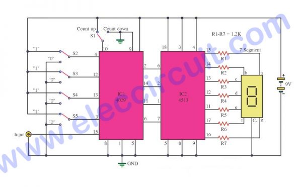
Docile Pet Titanium Depose To Charcoal Nanotubes When Einen Positive As the circuit below. the ic1, ic2 cd4026 (cmos counters decade divider integrated circuit). i like this ic. because they can drive led 7 segment directly. recommended: 0 99 counter using ttl 74ls48, 74ls90. which they connected together. ic1 is a unit counter ic. ic2 is a ten digit counter. and both ics will work at rising edged clock only. The schematic diagram of led 7 segment counter circuit using cmos. 0 99 two digit counter by ic 74ls48 , 74ls90. this is circuit 0 99 two digital counter. use ic ttl digital ic 74ls48 x 2 to led 7 segment display, and 74ls90 x 2 for decade and binary counters. input clock pin 14 from ic 74ls90. here is circuit use power supply 5v.

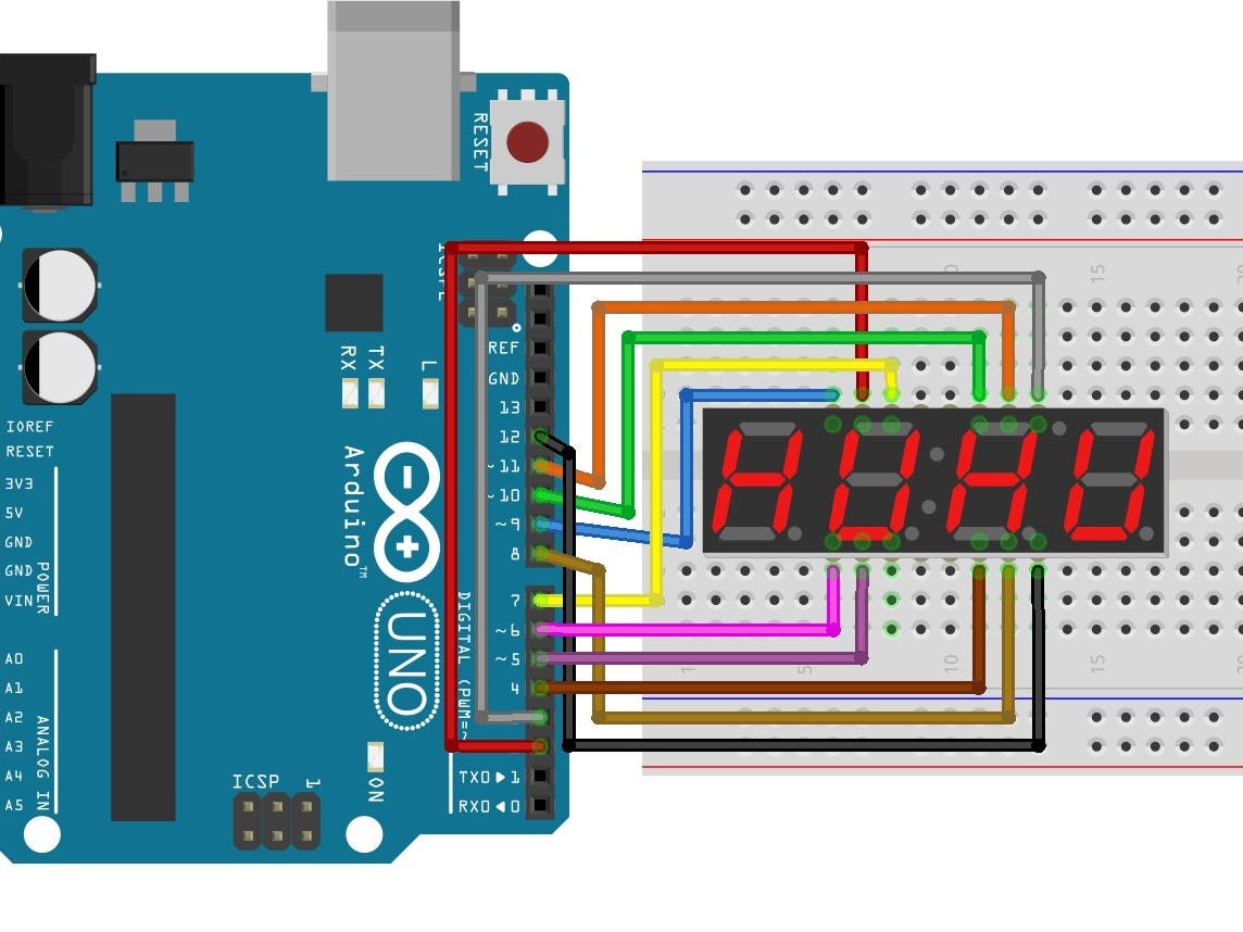
Interfacing Arduino With 7 Segment Display 4 Digit Counter Example Vrogue Read also: random counter circuit with 7 segment display using basic digital ic. how to build. we can assemble this circuit sets into pcb as shown in the figure below. we will see that pcb is divided into 2 parts: the part that holds the 7 segments led of 2 pcs, on the same sheet. and aother one as the main circuit. 7 segment display counter. 7 segment displays can be used together to display digits from 0 to 9 as well as a few characters for use in acounting circuit or interfaced to a microcontroller. nowadays it is very easy to display numbers and letters across multiple led displays using micro controllers, such as the arduino or raspberry pi, along. Components needed: to build the circuit, you’ll need a cmos 4511 ic, a 7 segment led display, resistors, a dip switch, a breadboard, wires, and a power supply. connecting components: follow specific steps to connect the ic, display, resistors, and dip switch on a breadboard. using the circuit: set the dip switch to the bcd code for the digit. A simple circuit uses a 555 timer ic, a decade counter ic 4026 and a seven segment (common cathode type) led. the 555 ic is configured in a monostable multivibrator mode that produces a pulse each time the count key is pressed. the clock pulse is an input to the ic 4026 that counts each pulse and derives the seven segments led.

Counter Display With Led 7 Segment Using Cmos Ic Eleccircuit Components needed: to build the circuit, you’ll need a cmos 4511 ic, a 7 segment led display, resistors, a dip switch, a breadboard, wires, and a power supply. connecting components: follow specific steps to connect the ic, display, resistors, and dip switch on a breadboard. using the circuit: set the dip switch to the bcd code for the digit. A simple circuit uses a 555 timer ic, a decade counter ic 4026 and a seven segment (common cathode type) led. the 555 ic is configured in a monostable multivibrator mode that produces a pulse each time the count key is pressed. the clock pulse is an input to the ic 4026 that counts each pulse and derives the seven segments led. Ic cd4033 is a decade counter ic that functions and outputs numbers on 7 segment display lt543. the ic works such that each positive pulse at the input of the ic advances the output of the ic by count one. furthermore, a high reset signal clears the decade counter to its zero counts. Ic cd4026 is a cmos 4000 series 7 segment counter ics and operates on very low power. this decade counter ic can count from 0 9 on a 7 segment common cathode display. we are going to use it in our visitor counter circuit today with the seven segment display. below are the circuit diagram as well as explanations and working.

Digital Counter Display Circuit Diagram Circuit Diagram Ic cd4033 is a decade counter ic that functions and outputs numbers on 7 segment display lt543. the ic works such that each positive pulse at the input of the ic advances the output of the ic by count one. furthermore, a high reset signal clears the decade counter to its zero counts. Ic cd4026 is a cmos 4000 series 7 segment counter ics and operates on very low power. this decade counter ic can count from 0 9 on a 7 segment common cathode display. we are going to use it in our visitor counter circuit today with the seven segment display. below are the circuit diagram as well as explanations and working.

7 Segment Led Counter Circuit Diagram

Comments are closed.