Cummins Cooling System Flow Chart

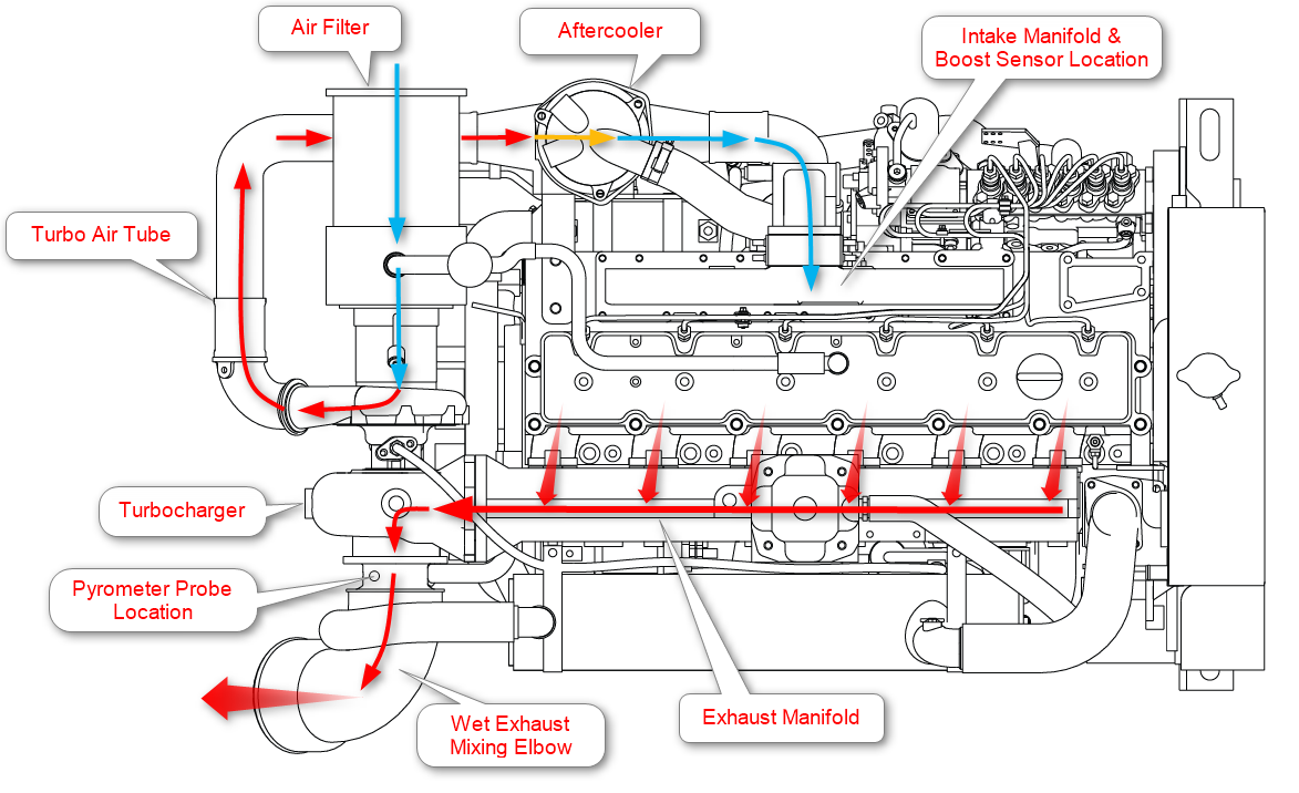
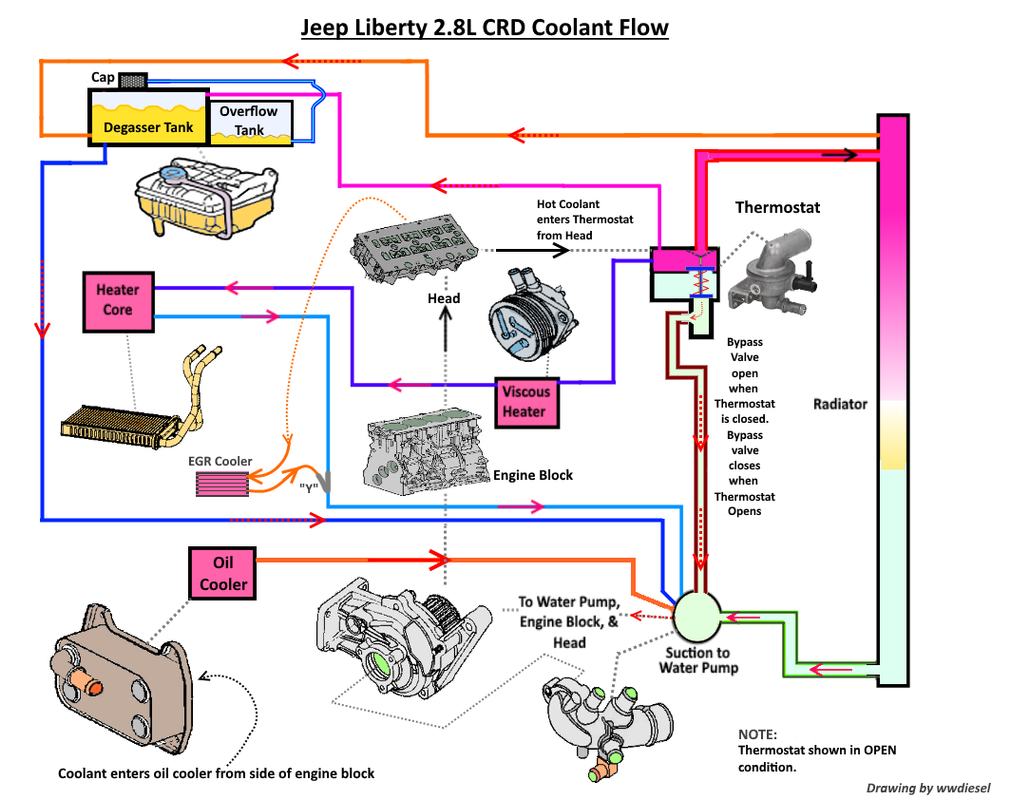
5 9 Cummins Coolant Flow Diagram A coolant flow diagram of a 67 cummins engine illustrates the path that coolant takes through the engine’s cooling system. understanding this diagram is crucial in maintaining optimal engine performance, preventing overheating, and reducing emissions. in the 67 cummins engine, the coolant flows from the water pump, through the engine, and. The coolant flow diagram is a vital component in the 5.9 cummins engine, as it allows for proper circulation of coolant to prevent overheating and ensure optimal performance. understanding the coolant flow diagram and the main components of the coolant system is essential for maintaining the engine’s health and performance. chevy 350 coolant.

5 9 Cummins Coolant Flow Diagram Sized for the ambient and components cho sen. typically the top tank temperature of the system (temperature at the inlet to the engine) will not exceed 220 ° f (104 c) for ° standby applications, and 200 f (93 c) for ° ° prime power installations. the cooling system must include deaeration. First the basics; coolant enters the radiator from the top, exits the bottom. coolant enters the water pump, flows up into the block, then up through the head, then forward through the thermostat, and back into the radiator. repeat. my question (s) are regarding the heat exchanger and heater core flow. 1) just above the water pump is the exit. 50 percent water. fully formulated coolant contains balanced amounts of antifreeze, sca, and buffering compounds already premixed 50 50 with deionized water. alternative maintenance practices for cooling systems can be found in cummins coolant requirements and maintenance, bulletin 3666132. it is unlawful to tamper with or remove any component. Manuals and technical documents | cummins inc.

Comments are closed.