Deflection Of Cantilever Beam Equation Slideshare

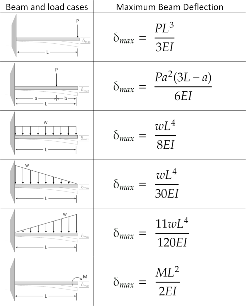
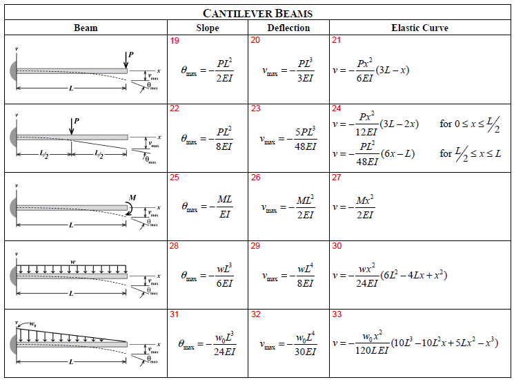
Cantilever Beam Displacement Formula Design Talk Using the load hanger mass is added at the center of beam. the deflection of beam is noted using the digital dial. zero correction is noted using the digital dial before adding any weight. now load is increased as per the table and the deflection of beam is noted. the process is repeated again and again for different weight. 1. the document provides formulas for calculating slope, deflection, and maximum deflection for various beam types under different loading conditions. it gives the equations for cantilever beams with concentrated loads, uniformly distributed loads, and varying loads. it also provides the equations for simply supported beams with these different.

Maximum Deflection Of Cantilever Beam With Point Load Mymagesvertical Oct 17, 2015 • download as pptx, pdf •. this document discusses beam deflection. it begins by defining beam deflection and the factors that affect it, including bending moment, material properties, and shape properties. it then presents the general formula for calculating beam deflection using double integration of the bending moment equation. Where: \ (m x \) = bending moment at point x \ (p \) = load applied at the end of the cantilever \ (x \) = distance from the fixed end (support point) to point of interest along the length of the beam. for a distributed load, the equation would change to: \ (m x = – ∫wx\) over the length (x1 to x2) where: w = distributed load x1 and x2 are. Slope and deflection in symmetrically loaded beams. maximum slope occurs at the ends of the beam. a point of zero slope occurs at the center line. this is the point of maximum deflection. moment is positive for gravity loads. shear and slope have balanced and areas. deflection is negative for gravity loads. Example cantilever beam with single load at the end, metric units. the maximum moment at the fixed end of a ub 305 x 127 x 42 beam steel flange cantilever beam 5000 mm long, with moment of inertia 8196 cm 4 (81960000 mm 4), modulus of elasticity 200 gpa (200000 n mm 2) and with a single load 3000 n at the end can be calculated as. m max.
Beam Deflection Table Cantilever Brokeasshome Slope and deflection in symmetrically loaded beams. maximum slope occurs at the ends of the beam. a point of zero slope occurs at the center line. this is the point of maximum deflection. moment is positive for gravity loads. shear and slope have balanced and areas. deflection is negative for gravity loads. Example cantilever beam with single load at the end, metric units. the maximum moment at the fixed end of a ub 305 x 127 x 42 beam steel flange cantilever beam 5000 mm long, with moment of inertia 8196 cm 4 (81960000 mm 4), modulus of elasticity 200 gpa (200000 n mm 2) and with a single load 3000 n at the end can be calculated as. m max. Character of the slope. our moment curvature equation can then be written more simply as x 2 2 d dv mb x ei = exercise 10.1 show that, for the end loaded beam, of length l, simply supported at the left end and at a point l 4 out from there, the tip deflection under the load p is pl3 given by ∆= (316 ⁄ )⋅ ei p a b c l 4 l. 2. cantilever beam – concentrated load p at any point 2 pa 2 e i lei 2 3for0 px yax xa 6 ei 2 3for pa yxaaxl 6 ei 2 3 pa 6 la ei 3. cantilever beam – uniformly distributed load (n m) 3 6 l e i 2 22 64 x yxllx ei 4 max 8 l e 4. cantilever beam – uniformly varying load: maximum intensity o 3 o 24 l e i 2 32 23 o 10 10 5 120 x yllxlxx 4 o.

Cantilever Beam Deflection Formula Design Talk Character of the slope. our moment curvature equation can then be written more simply as x 2 2 d dv mb x ei = exercise 10.1 show that, for the end loaded beam, of length l, simply supported at the left end and at a point l 4 out from there, the tip deflection under the load p is pl3 given by ∆= (316 ⁄ )⋅ ei p a b c l 4 l. 2. cantilever beam – concentrated load p at any point 2 pa 2 e i lei 2 3for0 px yax xa 6 ei 2 3for pa yxaaxl 6 ei 2 3 pa 6 la ei 3. cantilever beam – uniformly distributed load (n m) 3 6 l e i 2 22 64 x yxllx ei 4 max 8 l e 4. cantilever beam – uniformly varying load: maximum intensity o 3 o 24 l e i 2 32 23 o 10 10 5 120 x yllxlxx 4 o.

Deflection Of Cantilever Beam Equation Slideshare

Comments are closed.