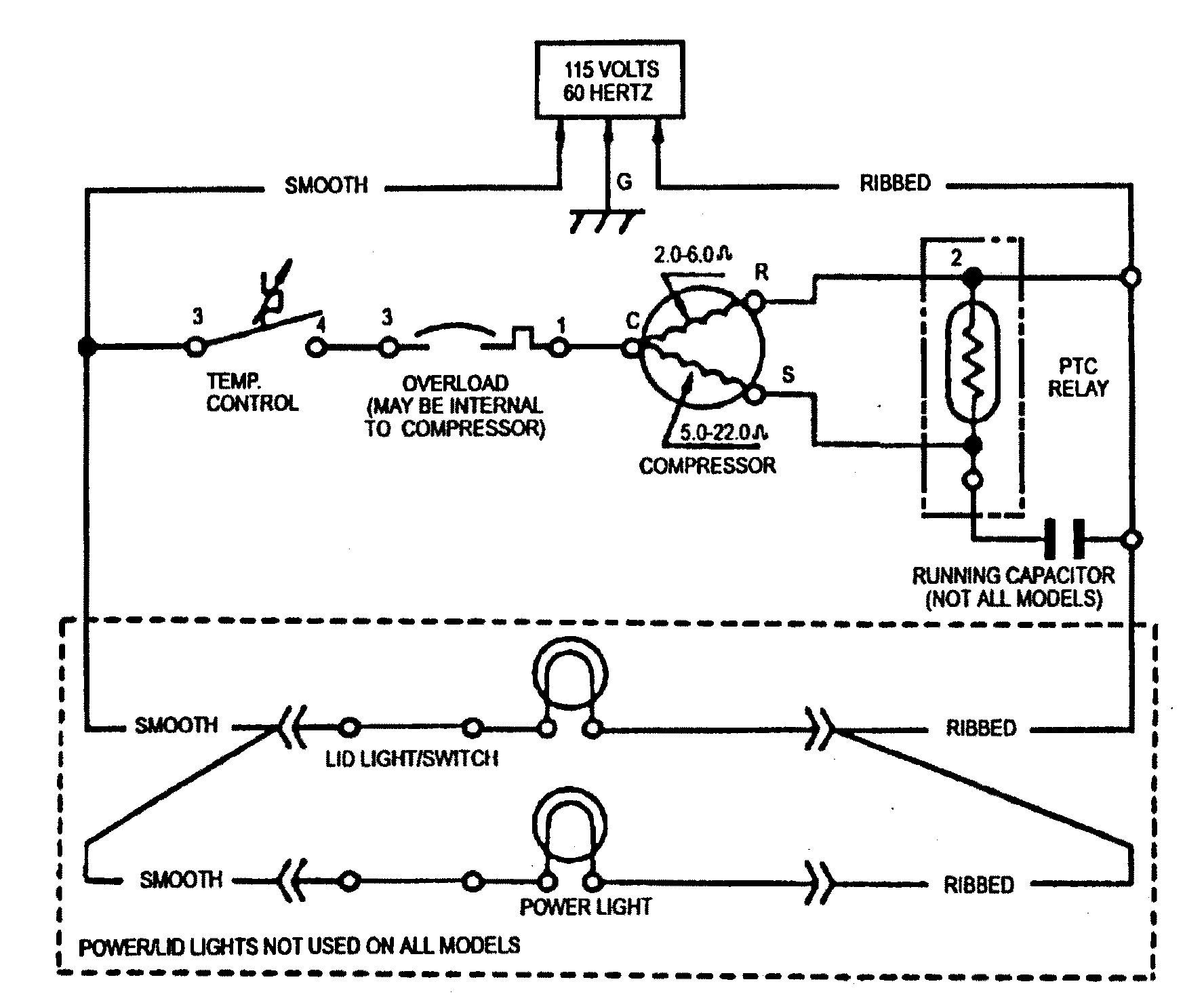
Defrost Timer Wiring Schematic

21340101 Timer Wiring Diagram For Defrost In this video you can learn about the defrost timer wiring diagram of a frost free refrigerator and circuit diagram step by step details about the function o. The paragon defrost timer 8145 20 wiring diagram is a multi stage installation process, involving three main features: the timer, the motor, and the relay. to begin, the timer needs to be connected to the motor and the relay. this is done by connecting wires from the timer to the motor's black and white connections.

Freezer Defrost Timer Wiring Diagram Herbalium In this video i will go over the defrost time clock wiring and troubleshootinginstagram instagram refrigerationkitchentechtik tok www. Welcome to our comprehensive guide on refrigerator defrost timers! in this video, we'll delve into the inner workings of these essential components, providin. The wiring diagram of the defrost timer illustrates the electrical connections and components involved in the defrosting process. it provides a clear representation of how the timer is wired to the refrigerator’s electrical system and other defrosting components. by referring to the whirlpool refrigerator defrost timer wiring diagram, you can. The wiring for a defrost timer can be complicated, and understanding the basics is essential for safely connecting your system. to begin, you’ll need to locate the main power source. this can typically be found near the thermostat, usually in the form of a thick black wire. once you’ve located the power source, you can connect the defrost.

Walk In Freezer Defrost Timer Wiring Diagram The wiring diagram of the defrost timer illustrates the electrical connections and components involved in the defrosting process. it provides a clear representation of how the timer is wired to the refrigerator’s electrical system and other defrosting components. by referring to the whirlpool refrigerator defrost timer wiring diagram, you can. The wiring for a defrost timer can be complicated, and understanding the basics is essential for safely connecting your system. to begin, you’ll need to locate the main power source. this can typically be found near the thermostat, usually in the form of a thick black wire. once you’ve located the power source, you can connect the defrost. The schematic diagram of a defrost timer illustrates the electrical connections and the sequence of operations that occur during the defrost cycle. the defrost timer schematic typically consists of several terminals labeled as common (c), line (l), and a series of numbered terminals (1, 2, 3, etc.) representing different time intervals. Page 3 dtmv40 typical wiring diagrams all switch positions are shown in refrigeration cycle operation, and change position upon initiation of a defrost. 8043 replacement 8045 replacement 8041 replacement mode b with 8043 label applied mode a with 8045 label applied mode a with 8041 label applied timer release.

Comments are closed.