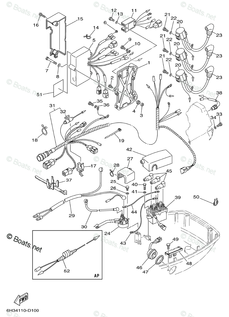
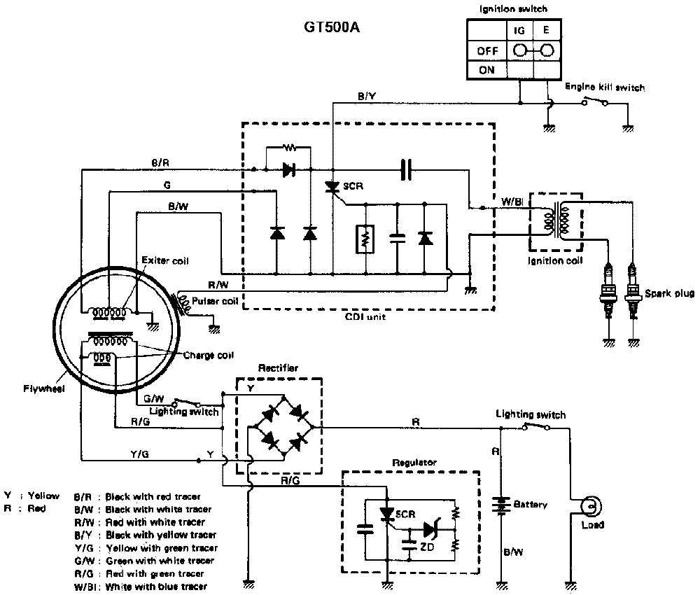
Diagram 2000 Yamaha 50 Hp 4 Stroke Wiring Diagram Mydiagram Onl

Diagram 2000 Yamaha 50 Hp 4 Stroke Wiring Diagra A yamaha 50 hp 4 stroke wiring diagram is a schematic drawing that outlines the wiring layout for a model of a four stroke engine. specifically, it is a representation of the electrical connections between the various components of the engine as well as other systems in a boat. this type of wiring diagram is commonly used by engine repair shops. This diagram offers a visual representation of the electrical system in the outboard motor, allowing for easier troubleshooting, repairs, and modifications. here are some of the key benefits of having a yamaha 50 hp outboard wiring diagram: 1. troubleshooting made easier: with a wiring diagram, boat owners and technicians can quickly identify.
Diagram 2000 Yamaha 50 Hp 4 Stroke Wiring Diagram Yamaha outboard motor wiring diagrams typically consist of various symbols and lines that represent different electrical components and their connections. for example, a battery symbol and lines indicate the power source, while different shapes and lines represent switches, circuit breakers, fuses, and wires. these symbols and lines are labeled. Key ‘on’ power yellow wire. the positive terminal of the battery, which has a small blue jumper that will only power the light bulb in the gauge, is where the key ‘on’ power enters. therefore, if you ever see a blue jumper wire, it’s usually only to backlight the gauge with light. thus a positive post here key ‘on’ power will. Follow the steps below to install your outboard yamaha tachometer. step 1: use a screwdriver to turn the selector switch to match the number of poles in your alternator for the correct rpm calibration. if you don’t know the number, consult the outboard tachometer application chart. step 2: to the tach stud marked “bat,” connect a yellow. Connect the power wire: locate a 12v power source on your boat’s electrical system. this can be a switched or constant power source. connect the power wire from the trim gauge to the positive terminal of the power source using a ring terminal and soldering the connection.

Diagram 2000 Yamaha 50 Hp 4 Stroke Wiring Diagra Follow the steps below to install your outboard yamaha tachometer. step 1: use a screwdriver to turn the selector switch to match the number of poles in your alternator for the correct rpm calibration. if you don’t know the number, consult the outboard tachometer application chart. step 2: to the tach stud marked “bat,” connect a yellow. Connect the power wire: locate a 12v power source on your boat’s electrical system. this can be a switched or constant power source. connect the power wire from the trim gauge to the positive terminal of the power source using a ring terminal and soldering the connection. It is an f75tlr. if you mention a 75hp yamaha you might get pages from a two stroke service manual. as noted, you can either buy the complete manual (preferred) or perhaps if you have a good relationship with your dealer he will give you a copy of the wiring diagram. Read this manual carefully before operating this outboard motor. owner’s manual f50 t50 f60 t60 f70 lit 18626 12 40 6c1 28199 3k e0 6c1 9 3k 1e0.book 1 ページ 2018年12月4日 火曜日 午後4時38分.

Comments are closed.