Diagram 6 Pin Din Plug Pinout Wiring Diagram Mydiagr

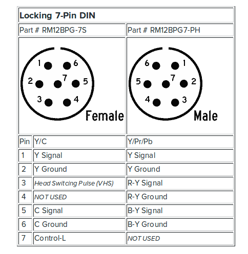
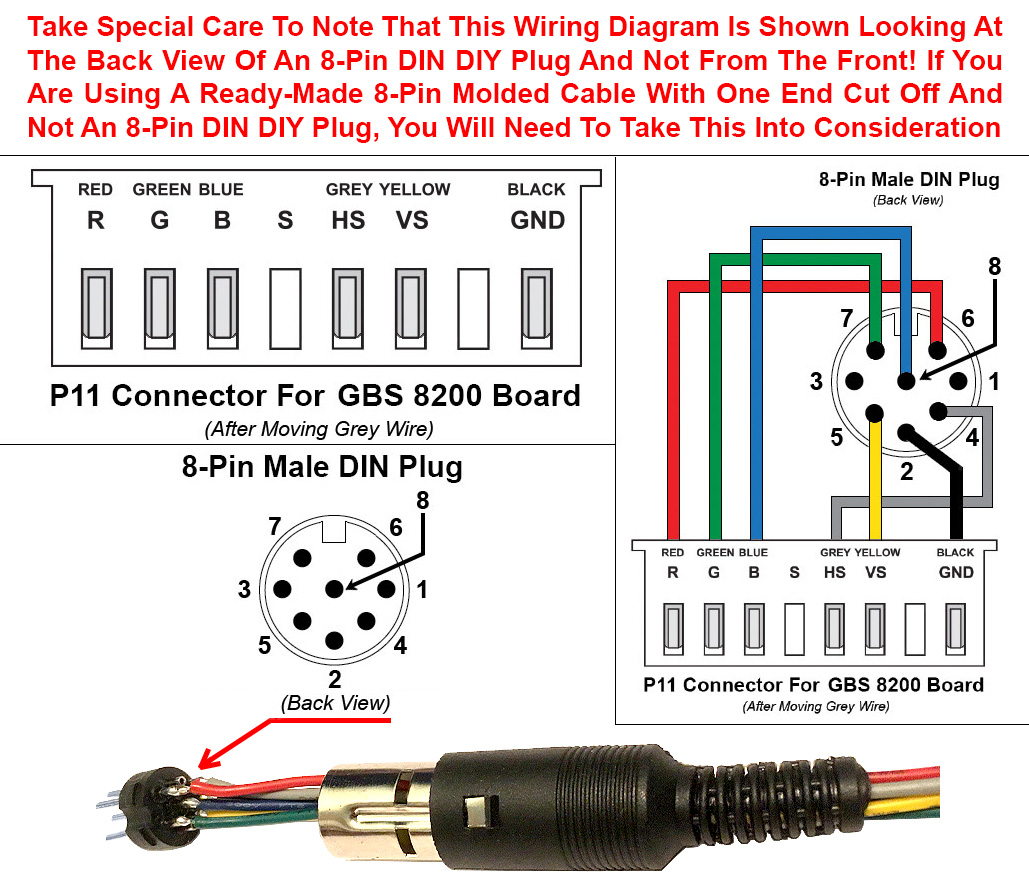
6 Pin Din Connector Wiring Diagram Pinout Image Of Connector Step 4: insert the wires into the connector. referencing the pinout diagram, begin inserting the stripped ends of the wires into the appropriate pins of the connector. ensure that each wire is securely inserted and has good contact with the metal pin inside the connector. The wiring diagram for a 6 pin connector shows the pin configuration and the corresponding functions of each pin. the 6 pin connector can be found in a variety of applications, including automotive, computer, and industrial equipment. each pin has a specific purpose, such as transmitting power, ground, data signals, or control signals.

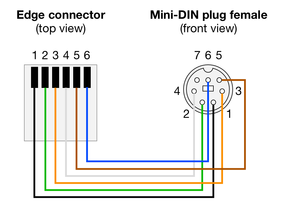
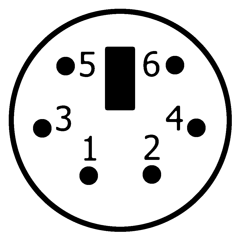
6 Pin Wiring Diagram 6 Pin Dpdt Switch Wiring Diagramођ While not a complete answer to the question, many vendors of circular connectors like mil 38999 (amphenol, for example) use the "looking into the mating side, or front" of the connector way. this is irrespective whether the connector is male or female, and whether or not the connector is chassis mounter (a jack) or cable mounted (a plug). 6 pin mini din wiring diagrams come in two types: one way and two way. the one way diagram shows one plug on the left side and one socket on the right side. the two way diagram shows two plugs on either side. these diagrams are further broken down into more specific categories to match the environment they are being used in. The 6 pin mini din connector consists of six pins labeled as follows: vcc, data, nc, gnd, clk, and nc. each pin has a specific function in the connection. the vcc pin provides power to the device, while the gnd pin is the ground connection. the data and clk pins are used for data transmission, with the data pin transmitting data from the device. English: the pinout of a 6 pin mini din connector (as viewed from the socket). deutsch: steckerbelegung für maus oder tastatur (sicht auf die buchse): 1 = datenleitung (data),.

9 Wiring Diagram 5 Pin Din Connector Pinout Image Of Vrogue Co The 6 pin mini din connector consists of six pins labeled as follows: vcc, data, nc, gnd, clk, and nc. each pin has a specific function in the connection. the vcc pin provides power to the device, while the gnd pin is the ground connection. the data and clk pins are used for data transmission, with the data pin transmitting data from the device. English: the pinout of a 6 pin mini din connector (as viewed from the socket). deutsch: steckerbelegung für maus oder tastatur (sicht auf die buchse): 1 = datenleitung (data),. 6 way plug wiring diagr am. g diagramstandard wiring*the most common variances on this diagram will be the (blue brake) & (red ac. ) wires will b. inverted. if there is nored or blue wire and there is both a black & a white wire, normally, the black will be b. akes and the white ground.* always test wires for fun. ion and wire accordingly. this. The pinout diagram for the rj11 6 pin connector is as follows: pin 1: line 1 – this pin is used to transmit the first line of the telephone signal. pin 2: line 2 – this pin is used to transmit the second line of the telephone signal. pin 3: line 3 – this pin is used to transmit the third line of the telephone signal.

Diagram Pinout 6 Pin Din Plug Wiring Diagram Mydiag 6 way plug wiring diagr am. g diagramstandard wiring*the most common variances on this diagram will be the (blue brake) & (red ac. ) wires will b. inverted. if there is nored or blue wire and there is both a black & a white wire, normally, the black will be b. akes and the white ground.* always test wires for fun. ion and wire accordingly. this. The pinout diagram for the rj11 6 pin connector is as follows: pin 1: line 1 – this pin is used to transmit the first line of the telephone signal. pin 2: line 2 – this pin is used to transmit the second line of the telephone signal. pin 3: line 3 – this pin is used to transmit the third line of the telephone signal.
6 Pin Mini Din Wiring Diagram Wiring Diagram And Schematic

Comments are closed.