Diagram Ford Ranger Cooling System Diagram Mydiagram Online

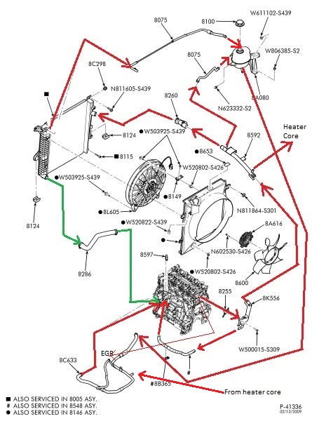
Diagram Ford Ranger Cooling System Diagram Mydiagram Online Engine type. 2.3 ecoboost. nov 27, 2022. #1. good afternoon! i'm hoping someone may be able to lend a hand. i have a complete 2020 ecoboost drivetrain i'm doing a swap with. unfortunately many of the stock hoses were cut when it was removed. i was able to find a single diagram online for the cooling system but it is blurry. 6 inches. tire size. 33x12.50x15. dec 23, 2018. #1. looking for photos, test drive videos, technical specifications, diagrams, and exploded views related to the 2019 2023 ford ranger. visit the introduction 2019 ford ranger page, or check out: 2019 ford ranger links. here are some articles (links) and assorted documents to help familiarize.

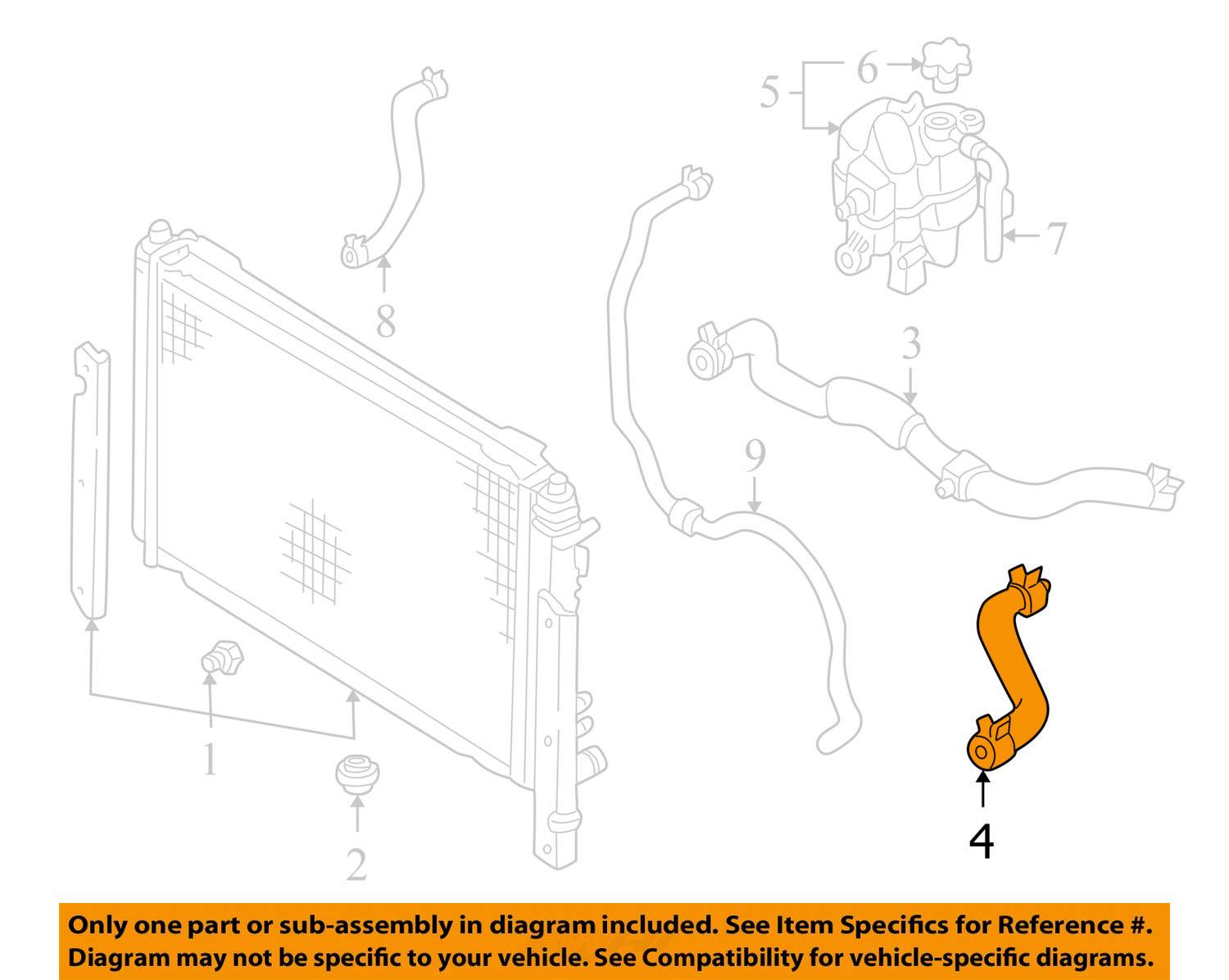
Diagram Ford Ranger Cooling System Diagram Mydiagram Online The ac system of the ford ranger consists of various components that work together to provide cold air inside the cabin. these components include the compressor, condenser, evaporator, receiver drier, expansion valve, and refrigerant. the compressor plays a crucial role in pressurizing and circulating the refrigerant throughout the system. The ford ranger cooling system diagram provides a clear overview of how the cooling system works to keep your ford ranger running at its optimum performance level. this diagram clearly identifies the major components of the cooling system, such as the radiator, water pump, thermostat, hoses and other related parts. The ac diagram for a ford ranger typically includes the following components: the compressor, condenser, evaporator, expansion valve, receiver, and drier. the compressor is responsible for pressurizing the refrigerant and pumping it through the system. the refrigerant then flows to the condenser, where it is cooled by the airflow from the outside. Summary of contents for ford ranger 1998. page 1 1998 ranger workshop manual section 303 01b: engine — 3.0l 1998 ranger workshop manual in vehicle repair procedure revision date: 03 03 2000 intake manifold—lower special tool (s) fuel pressure gauge t80l 9974 b removal 1. disconnect the battery ground cable. refer to section 414 01.

Comments are closed.