Diagram Shear Force And Bending Moment Diagram Solved Exampl

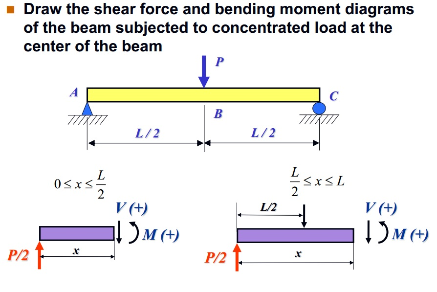
Diagram Shear Force And Bending Moment Diagram Solved Shear force and bending moment diagram example #4: applied moment; shear force and bending moment diagram example #5: mixed distributed and point loads; the quick way to solve sfd & bmd problems. shear force and bending moment diagram practice problem #1; shear force and bending moment diagram practice problem #2; shear force and bending moment. Plots of v(x) v ( x) and m(x) m ( x) are known as shear and bending moment diagrams, and it is necessary to obtain them before the stresses can be determined. for the end loaded cantilever, the diagrams shown in figure 3 are obvious from eqns. 4.1.1 and 4.1.2. figure 4: wall reactions for the cantilevered beam.

Shear And Bending Moment Diagrams Examples This video explains how to draw the shear force sfd and bending moment diagram bmd for a beam under a distributed load.here are the steps you should follow w. Equation 6.2 states that the change in moment equals the area under the shear diagram. similarly, the shearing force at section x dx is as follows: v x dx = v −wdx v dv = v − wdx v x d x = v − w d x v d v = v − w d x. or. dv dx = −w(x) d v d x = − w (x) (equation 6.3) equation 6.3 implies that the first derivative of the. To create the moment diagram for a shaft, we will use the following process. solve for all external forces and moments, create a free body diagram, and create the shear diagram. lined up below the shear diagram, draw a set of axes. the x axis will represent the location (lined up with the shear diagram and free body diagram above), and the y. Since the function for the bending moment is parabolic, the bending moment diagram is a curve. in addition to the two principal values of bending moment at x = 0 m and at x = 5 m, the moments at other intermediate points should be determined to correctly draw the bending moment diagram. the bending moment diagram of the beam is shown in figure.

Diagram Shear Force And Bending Moment Diagram Solved Exa To create the moment diagram for a shaft, we will use the following process. solve for all external forces and moments, create a free body diagram, and create the shear diagram. lined up below the shear diagram, draw a set of axes. the x axis will represent the location (lined up with the shear diagram and free body diagram above), and the y. Since the function for the bending moment is parabolic, the bending moment diagram is a curve. in addition to the two principal values of bending moment at x = 0 m and at x = 5 m, the moments at other intermediate points should be determined to correctly draw the bending moment diagram. the bending moment diagram of the beam is shown in figure. Select from the following links of solved examples. problem 5 3 calculate the values and draw the diagram for shear force and bending moment for a simply supported beam with overhang. problem 5 2 calculate the values and draw the diagram for shear force and bending moment for a simply supported beam subjected to point load and uniform load. Separated by a distance or lever arm, z. z z. you might recognise this pair of forces as forming a couple or moment m m. m = f c\times z = f t\times z \tag {2} m = f c ×z =f t ×z (2) 💡 the internal bending moment m m, is the bending moment we represent in a bending moment diagram. the bending moment diagram shows how m m (and therefore.
Shear Force And Bending Moment Diagram In The Horizontal Plane Select from the following links of solved examples. problem 5 3 calculate the values and draw the diagram for shear force and bending moment for a simply supported beam with overhang. problem 5 2 calculate the values and draw the diagram for shear force and bending moment for a simply supported beam subjected to point load and uniform load. Separated by a distance or lever arm, z. z z. you might recognise this pair of forces as forming a couple or moment m m. m = f c\times z = f t\times z \tag {2} m = f c ×z =f t ×z (2) 💡 the internal bending moment m m, is the bending moment we represent in a bending moment diagram. the bending moment diagram shows how m m (and therefore.

Comments are closed.