Diagrams Of Electricity

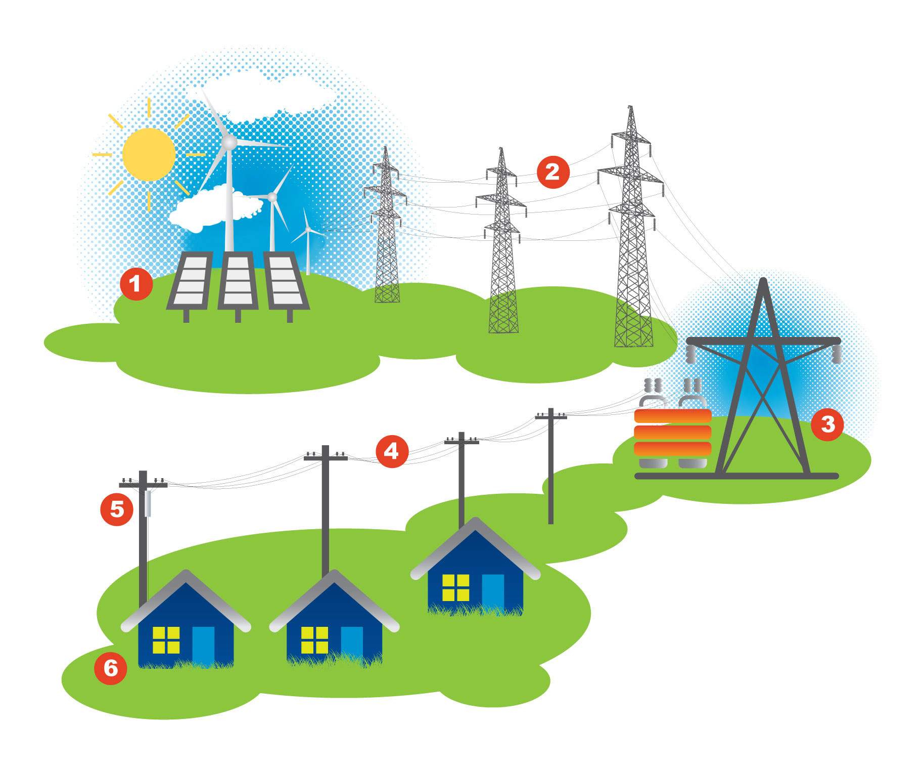
Diagram Of How Electricity Is Generated Electric circuit | diagrams & examples. Circuit symbols and circuit diagrams.

Simple Electric Current Diagram How to read electrical schematics. A basic electrical circuit (diagram) consists of three main components: the source, the load, and the conductors. the battery has two terminals. these terminals are connection points for the two conductors. one terminal is marked with a plus sign ( ) and the other a negative sign (–). these two markings are referred to as polarity markings. In effect, the circuit diagram is the language of electrical design and engineering. when engineers design or build any electrical circuit they either create or use an existing circuit diagram. interpreting circuit diagrams is an essential skill for electrical engineers and many other types of engineers. figure 2. Electrical symbols | electronic symbols | schematic symbols.

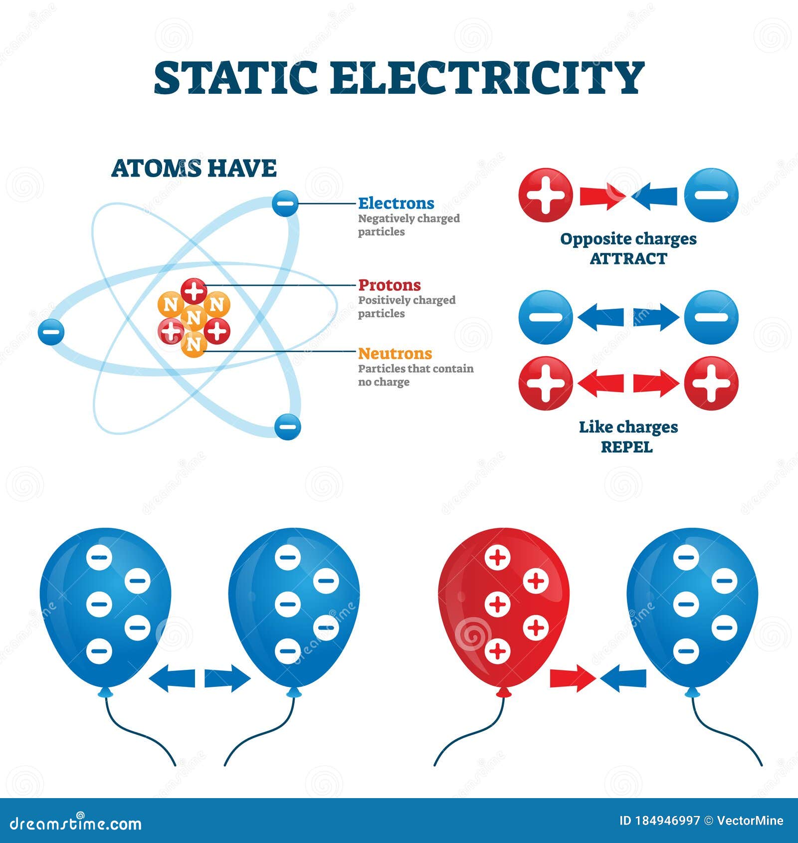
Static Electricity Vector Illustration Charge Energy Explanation In effect, the circuit diagram is the language of electrical design and engineering. when engineers design or build any electrical circuit they either create or use an existing circuit diagram. interpreting circuit diagrams is an essential skill for electrical engineers and many other types of engineers. figure 2. Electrical symbols | electronic symbols | schematic symbols. An electrical schematic, also known as a wiring diagram or circuit diagram, is a visual representation of an electrical circuit. it shows the electrical components and interconnections of the circuit using standardized symbols and lines. electrical schematics are used by electricians, engineers, and technicians to understand and troubleshoot. A circuit diagram (or: wiring diagram, electrical diagram, elementary diagram, electronic schematic) is a graphical representation of an electrical circuit. a pictorial circuit diagram uses simple images of components, while a schematic diagram shows the components and interconnections of the circuit using standardized symbolic representations.

Comments are closed.